82 INTAKE, INLET, AND EXHAUST M ANIF OLDS
Figure 71 Intake air heater – dual element
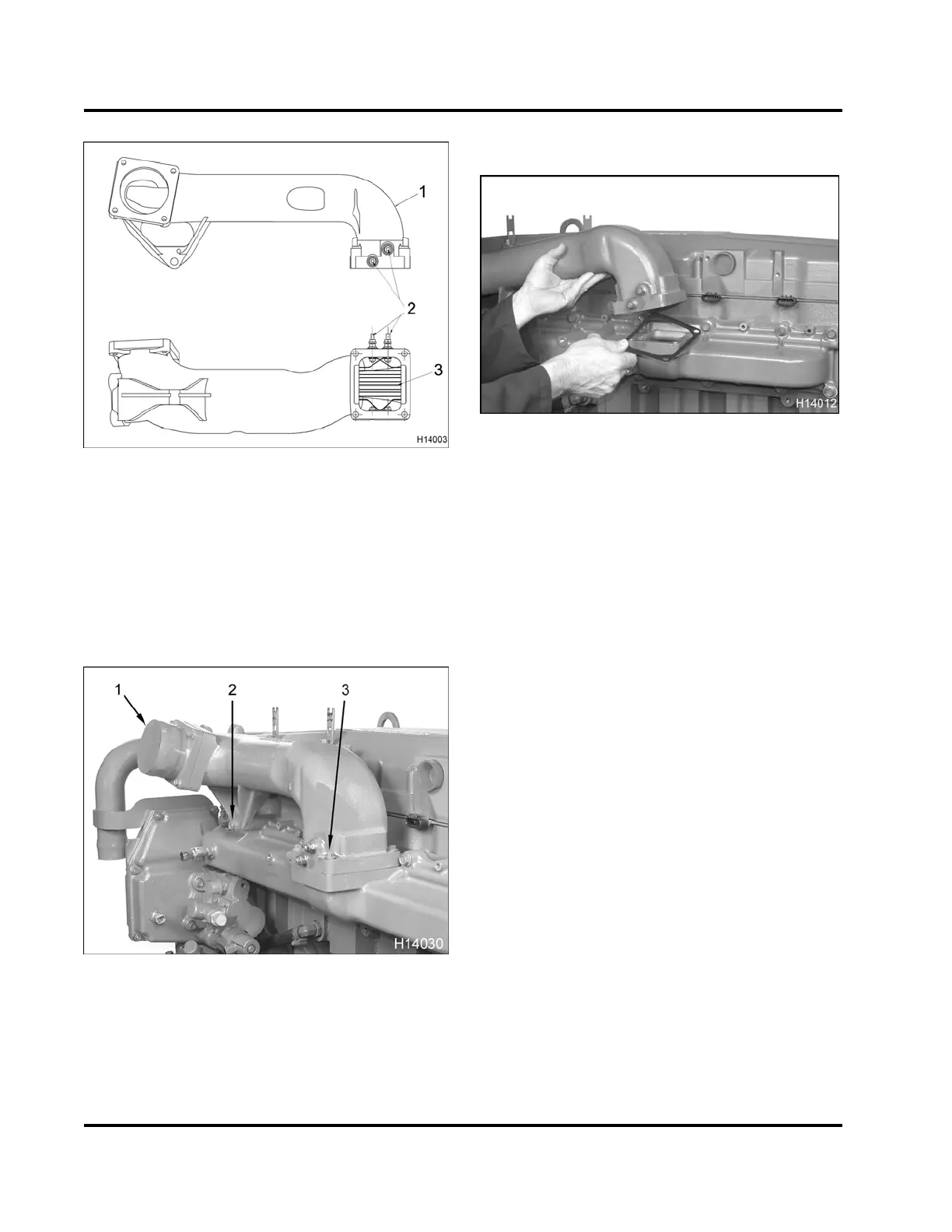
1. Inlet and EGR mixer
2. Intake air heater cable locations
3. Intake air heater element
See (TSI-05-12-35 New 1500 Watt Single Grid Intake
Air Heater Production Option, page466).
3. Disconnect Inlet Air Heater (IAH) cable(s).
Figure 72 Inlet and EGR mixer duct bolts
1. Inlet adapter
2. Inlet and EGR mixer support bolt, M10 x 90
3. Inlet mixer bolt, M8 x 60 (4)
4. Remove the inlet and EGR mixer duct bolts.
Figure 73 Inlet and EGR mixer duct gasket
5. Lift inlet and EGR mixer duct away from the in
take
manifold. Remove gasket and discard.
Aluminum Air Inlet Adapter and Inlet A
ir Heater
Option
See (1171846R1 Aluminum Air Inlet Ada
pter, page
492).
Intake Manifold
1. Disconnect wire from MAP and MAT s
ensor
connectors.
2. Disconnect injector harness anc
hor points.
3. Pull out wiring harness and conne
ctors.
4. Disconnect the high-pressure o
il hose at pump.
EGES-265-2
Read all safety instructions in the "Safety Information" section of this manual before doing any procedures.
Follow all warnings, cautions, and notes.
© 2009 Navistar, Inc.
 Loading...


