FUEL SYSTEM 357
1
2
3
H11052
Figure 565 IPR orientation
1. Fitting assembly, M18
2. Bolt,M8x100(2)
3. Bolt, M8 x 30 (2)
3. Install two bolts (M8
x 100) behind pump and
two bolts (M8 x 30) ou
tside, securing the
high-pressure pump
to the front cover. Tighten
bolts to the specia
l torque value (Table 47).
High-pressure Hose Assembly – Generation 1
Figure 566 Installation of high-pressure hose
assembly
1. Install a new O-ring seal onto the high-pressure
pump assembly before installing the
high-pressure hose assembly. Tighten swivel nut
by hand.
2. Install a new O-ring seal onto the high-pressure
fitting (M18) at the cylinder head before installing
the high-pressure hose assembly.
3. Orient hose fitting assembly at the cylinder head
at 0°± 7° relative to horizontal. Tighten swivel nut
by hand.
4. Using a crowfoot, tighten both swivel nuts to the
special torque value (Table 47) making sure hose
is not under any excess tension.
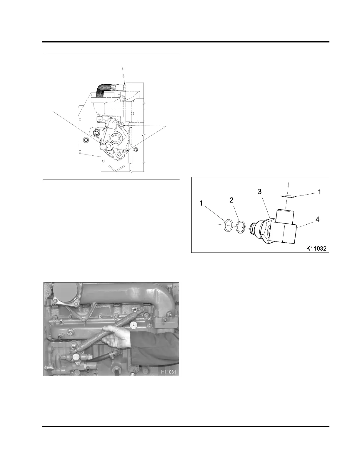
High-pressure H ose Assembly with 70 and 90
Degree Elbows – Generation 2
Figure 567 High-pressure oil elbow (typical)
1. O-ring seal (#14) (2)
2. Back-up ring
3. Elbow jam nut
4. Elbow
1. Rotate both elbow jam nuts all the way to the base
of the elbows.
2. Install new O-rings and back-up ring on the 70 and
90 degree elbows.
3. Lubricate new O-rings with clean engine oil.
CAUTION: To prevent engine damage, make all
adjustments to the high-pressure oil elbows within 15
minutes of applying Loctite®.
4. Apply two beads of Loctite® 246 Threadlocker
(Table 48) to the threads of both high-pressure oil
elbows.
EGES-265-2
Read all safety instructions in the "Safety Information" section of this manual before doing any procedures.
Follow all warnings, cautions, and notes.
© 2009 Navistar, Inc.
 Loading...


