INTAKE, INLET, AND EXHAUST MANIFOLDS 83
Figure 74 Intake manifold mounting bolts
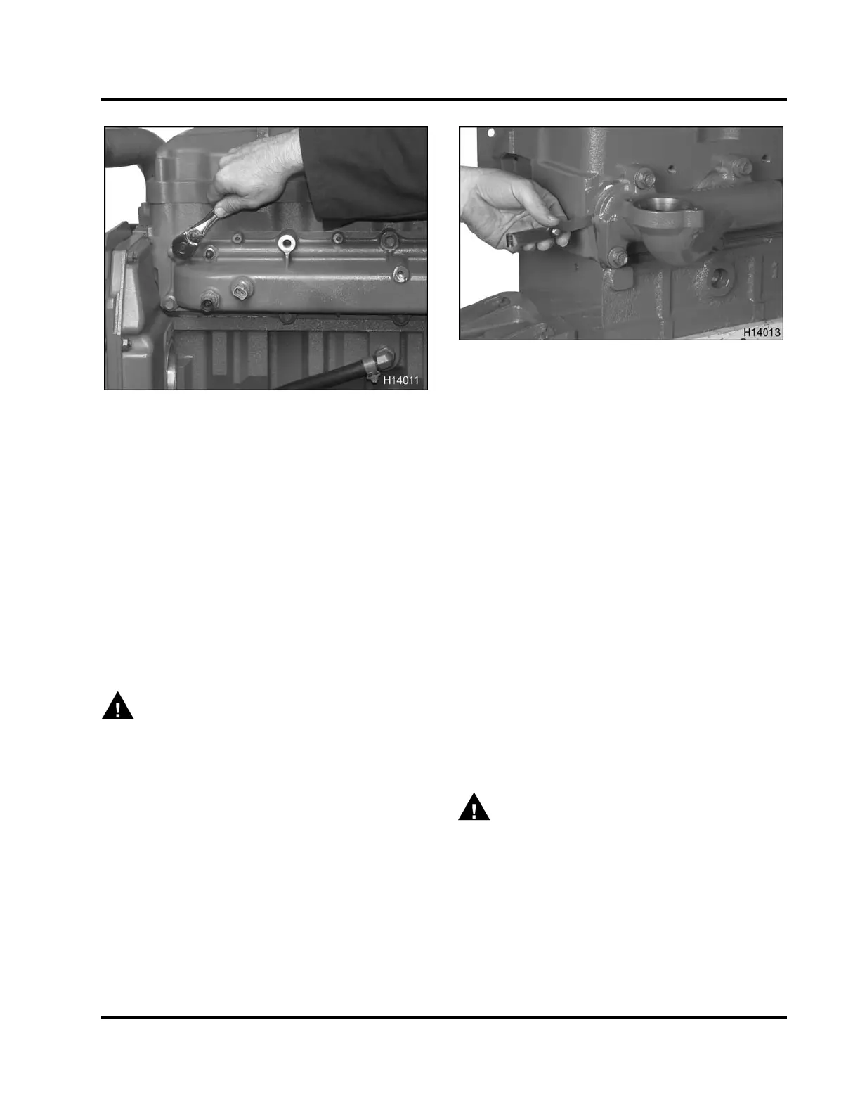
5. Remove 13 intake manifold mounting bolts (M10
x35).
6. Remove intake manifold and gasket from the
engine. Discard gasket.
Cleaning and Inspection
Exhaust Manifold
1. Clean exhaust manifold thoroughl
y with a suitable
non-caustic solvent. Scrape off
excess scale and
rust from manifold surfaces.
WARNING: To prevent personal in
jury or
death, wear safety glasses w
ith s ide s hields.
Limit compressed air pressu
reto207kPa(30psi).
2. After cleaning, blow dry exh
aust manifold using
filtered compressed air.
3. Inspect manifold for cracks
or damage. Replace
manifold as necessary.
4. Check for warpage as follo
ws:
a. Install exhaust manifold
without the gasket
to a cleaned cylinder hea
dmatingsurface.
Torque 12 mounting bolts
(M12 x 35) to the
special torque value (T
able 8).
Figure 75 Checking exhaust manifold for cracks
and warpa ge
b. Use a 0.25 mm (0.010 in) feeler gauge
to measure the gap between the mating
surfaces of the manifold and engine. If the
feeler gauge passes through the gap, the
manifold must be resurfaced.
NOTE: A maximum of 0.64 mm (0.025 in) of
material can be ground off to correct
warpage.
c. Remove 12 bolts (M12 x 35) and manifold
.
d. If the warpage cannot be corrected by
grinding manifold mating surface, r
eplace
manifold.
Intake Manifold
CAUTION: To prevent engine damag
e, do not attempt
to grind or machine the intake ma
nifold to compensate
for a warped condition.
1. Clean intake manifold thorou
ghly with a suitable
non-caustic solvent.
WARNING: To prevent persona
l injury o r
death, wear safety glasses
with side shields.
Limit compressed air pre
ssure to 207 kPa (30 psi).
2. After cleaning, blow dry
using filtered compressed
air.
3. Check manifold for crack
s and damage. Replace
intake manifold as nece
ssary.
EGES-265-2
Read all safety instructions in the "Safety Information" section of this manual before doing any procedures.
Follow all warnings, cautions, and notes.
© 2009 Navistar, Inc.
 Loading...


