EVRT® ELECTR ONICALLY CONTROLLED TUR BOCHA RGER 73
Inspection
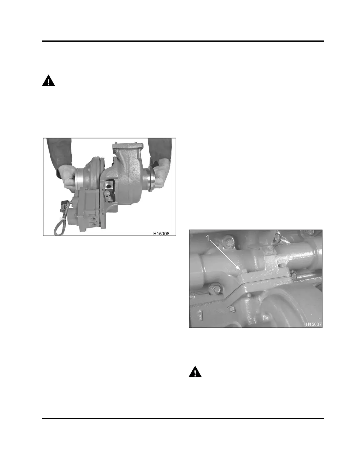
Checking Turbine and Compressor
WARNING: To prevent personal injury or
death, inspect turbocharger with engine off,
and turbocharger not spinning. Turbocharger
components may be extremely hot. Turbocharger
wheels are very sharp and spin at high speeds.
1. Position VGT on a workbench so that the shaft is
horizontal.
Figure 61 Checking shaft rotation
2. Turn shaft by hand and check for wheel rub within
each housing.
The wheels must rotate freely. If there is
any rubbing or interference, replace the VGT
assembly.
NOTE: Do not straighten bent blades.
3. Check the compressor impeller and turbine
wheel. If there are deposits on the blades or any
blades are bent, broken or eroded, replace the
VGT assembly.
Checking Rotation of Actuator Shaft
1. Place VGT assembly onto a clean workbench.
2. Position VGT assembly so that actuator linkage
can be easily accessed and viewed.
3. Move the actuator shaft through its entire travel.
The actuator shaft should rotate 90° and return
under spring tension (Table 5).
Installation
Variable Geometry Turbocharger (VGT) Assembly
1. Position VGT on a workbench so the oil supply
port faces up.
2. Prelube the VGT assembly by adding oil to the
oil supply port while rotating the turbine shaft.
Continue to add oil until oil comes out the oil drain
port.
3. Place a new turbocharger mounting gasket onto
turbocharger flange studs.
4. Place a new O-ring onto each end of the
turbocharger oil drain tube and lubricate with
clean engine oil.
CAUTION: To prevent serious personal injury,
possible death, or damage to the engine or vehicle,
exercise special care not to cut or damage oil drain
tube O-rings.
5. Install oil drain tube into turbocharger side and
then move turbocharger and oil drain tube int
o
cylinder block as a unit.
Figure 62 VGT mounting
1. M10 Spiralock® nut (4)
WARNING: To prevent personal injury or
death, support turbocharger assembly during
removal and installation.
6. Lift VGT assembly onto engine and insert VGT
mounting studs into the exhaust manifold flange.
EGES-265-2
Read all safety instructions in the "Safety Information" section of this manual before doing any procedures.
Follow all warnings, cautions, and notes.
© 2009 Navistar, Inc.
 Loading...


