74 EVRT® ELEC TRONICA LLY CONTROLLED TURBOC HA RGER
Install two new M10 Spiralock® nuts on the VGT
mounting studs.
7. Install two new M10 Spiralock® nuts on the
exhaust manifold studs.
8. Verifytheoildraintubeisseatedinthecrankcase
oil drain port.
9. Tighten four M10 Spiralock® nuts to the special
torque (Table 6).
Figure 63 Oil drain tube bracket and bo
lt
10. Align oil drain tube bracket with
bolt (M8 x 16) and
hole and tighten bolt to the stand
ard torque value
(General Torque Guidelines, pa
ge445).
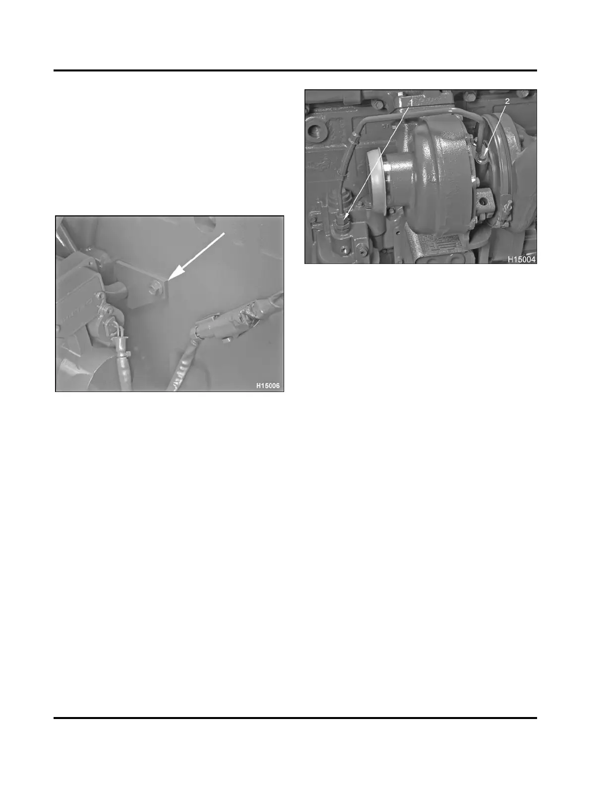
11. Place a new turbo oil inlet O-rin
g over oil inlet
flange located on top of the VGT ce
ntral housing.
Figure 64 Oil inlet tube ass embly
1. Nut
2. Bolt, M8 x 20 (2)
12. Thread two bolts (M8 x 20) through turbo oil
inlet
tube assembly at the top of the VGT. Do not
tighten these bolts yet.
13. Thread oil inlet tube assembly nut on
to fitting
locatedontopofoilfilter header.
14. Tighten two bolts (M8 x 20) at the top o
f the oil
inlet tube assembly to the standard
torque value
(General Torque Guidelines, pa
ge445).
15. Tighten oil inlet tube assembly n
ut to the standard
torque value (General Torque Gu
idelines, page
445).
16. Connect electrical harness to V
GT actuator.
EGES-265-2
Read all safety instructions in the "Safety Information" section of this manual before doing any procedures.
Follow all warnings, cautions, and notes.
© 2009 Navistar, Inc.
 Loading...


