DIAMOND LOGIC® ENGINE BRAKE 399
Removal
Valve Cover
1. Remove valve cover. See (Valve Cover, page120)
in the “Cylinder Head and Valve Train” section of
this manual.
Electrical Connectors
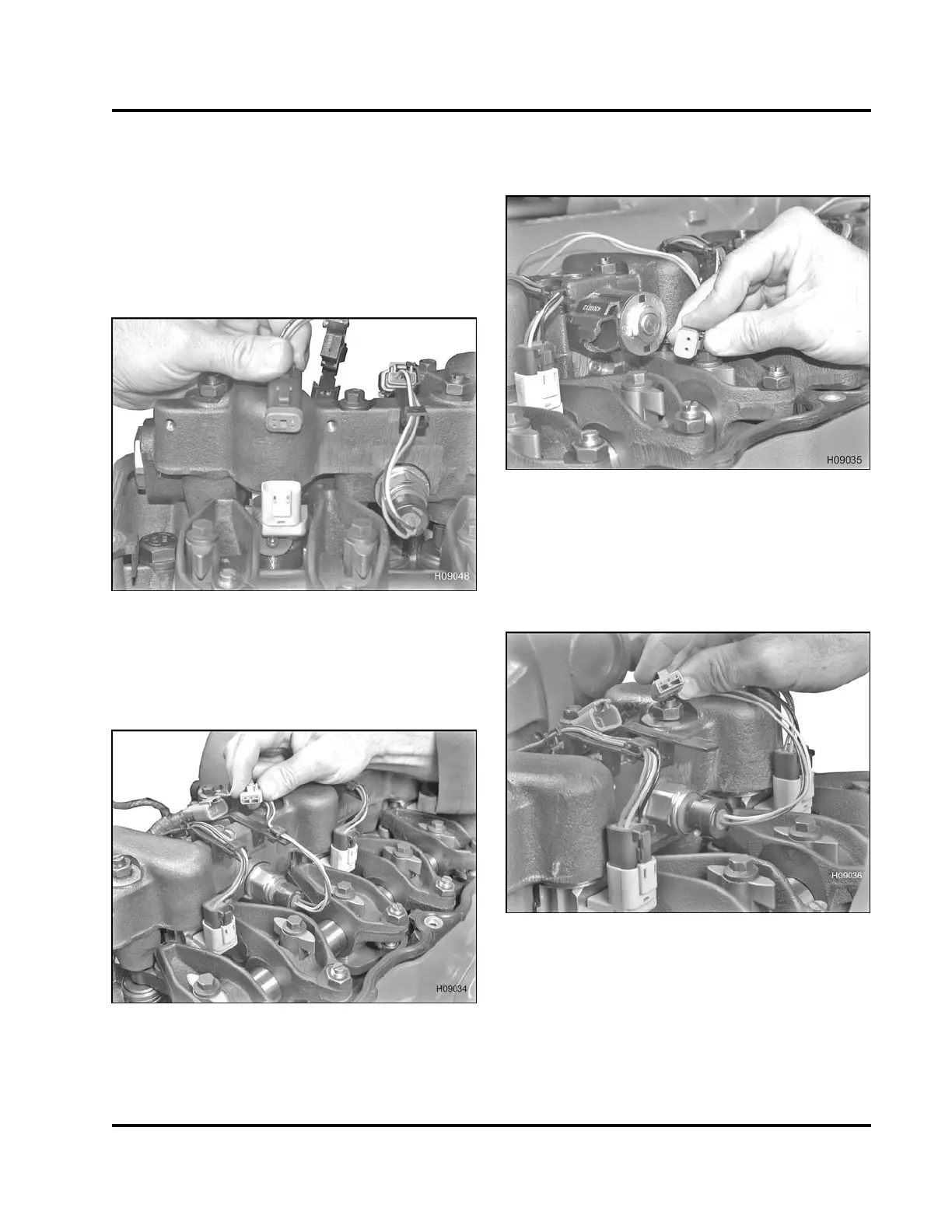
Figure 636 Injector electrical connector
1. Unclip and disconnect each injector electrical
connector from the high-pressure oil rail and
valve cover gasket and place aside.
Figure 637 ICP sensor electrical connector
2. Unclip and disc
onnect the Injection Control
Pressure (ICP)
sensor electrical connector from
the high-pressure oil rail and valve cover gasket
(rear).
Figure 638 Brake shutoff valve assembly
electrical connector
3. Unclip and disconnect Brake Shutoff Valve (BSV)
electrical connector from the high-pressure oil rail
and valve cover gasket.
Figure 639 BCP sen
sor electrical connector
4. Unclip and disco
nnect Brake Control Pressure
(BCP)sensorele
ctrical connector from the
high-pressure
oil rail and valve cover gasket
(front).
NOTE: The ICP a
nd BCP sensors are identical and
share the sam
e part number.
EGES-265-2
Read all safety instructions in the "Safety Information" section of this manual before doing any procedures.
Follow all warnings, cautions, and notes.
© 2009 Navistar, Inc.
 Loading...


