FUEL SYSTEM 359
each elbow, while using another wrench to tighten
the elbow jam nut to special torque value (Table
47).
10. Install the conduit cover onto the high-pressure
hose.
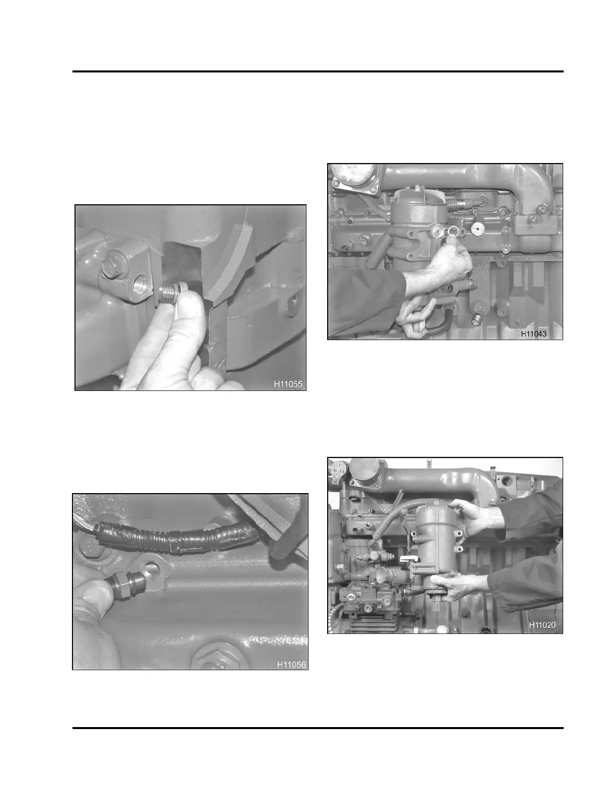
Fuel Filter Header Assembly and Intake Manifold
Figure 571 Installing the fuel rai
l plug assembly
(2)
1. Install a new O-ring seal onto the plug assembly
(M12) and install into each end of intake manifold.
Tighten plug to the special torque value (Table 47).
Figure 572 In
stalling the fuel valve assembly
(air bleed an
d p ressure test port)
2. Install a new O-ring seal onto the fuel valve
assembly (air bleed and pressure test port) and
install into port located towards the front of the
intake manifold. Tighten to the special torque
value(Table47).
Figure 573 Installing the fuel filter outlet gasket
3. Coat the fuel filter outlet gasket with petroleum
jelly and set into recess located on backside of fuel
filter header. The petroleum jelly will help it stay
in position while the filter header is being oriented
into position.
Figure 574 Inst
alling fue l filter header
4. Install the f
uel filter header and three mounting
bolts(M8x10
0) to the intake manifold.
EGES-265-2
Read all safety instructions in the "Safety Information" section of this manual before doing any procedures.
Follow all warnings, cautions, and notes.
© 2009 Navistar, Inc.
 Loading...


