182 FRONT COVER AND RELAT ED COMPONENTS
Idler Gea rs
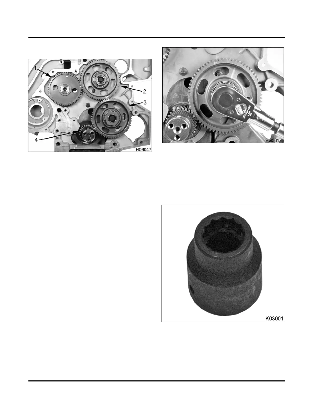
Figure 247 Gears and timing marks
1. Camshaft gear
2. Upper idler gear
3. Lower idler gear
4. Crankshaft gear
NOTE: When installing the gears in the gear train,
thetimingmarksontheedgeofeachgearmustbe
correctly aligned and oriented (facing outward). Once
the gears are properly installed, the crankshaft will
require 34 revolutions to align the timing marks again.
• The upper idler gear and camshaft gear are
matched with one dimple on each gear
• The upper idler gear and lower idler gear are
matched with two dimples on each gear
• The lower idler gear and crankshaft gear are
matched with one dimple on each gear
Figure 248 Installing the lower idler gear
mounting bolt
1. Install and hand tighten the lower idler gear and
mounting bolt (M20 x 70) with timing marks facing
outward. Align single timing marks between the
crankshaft and lower idler gear.
Figure 249 Lower Idler Gear Socket
2. Tighten the M20 x 70 bolt to the special torque
value (Table 20) using Lower Idler Gear Socket
(Table 21).
EGES-265-2
Read all safety instructions in the "Safety Information" section of this manual before doing any procedures.
Follow all warnings, cautions, and notes.
© 2009 Navistar, Inc.
 Loading...


