166 FRONT COVER AND RELAT ED COMPONENTS
2. Tap water inlet elbow with a hammer to break
coolant seal. Remove water inlet elbow and
discard gasket seal.
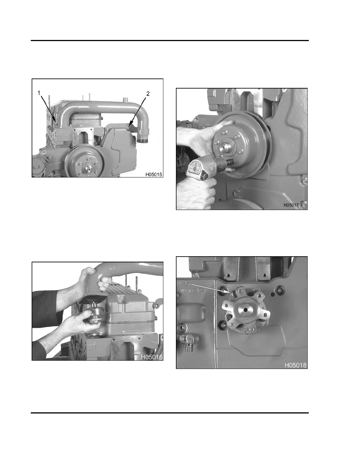
Figure 217 Water outlet tube assembly
1. Bolt, M8 x 25 (2)
2. Hex flange nut, M8 (2)
3. Remove two water outlet tube assembly bolts (M8
x 25) at the cylinder head.
4. Remove two hex flange nuts (M8) retaining the
water outlet tube assembly to front cover and
remove tube assembly.
Figure 218 Thermostat assembly
5. Lift thermos
tat out of cylinder head.
NOTE: The thermostat seal cannot be purchased
separately. It is only available with the thermostat
assembly.
Fan Drive Hub
Figure 219 Removing the fan drive pulley
1. Remove six hex flange bolts (M8 x 20) and the fan
drive pulley.
Figure 220 Fan h
ub assembly (typical)
1. Bolt, M8 x 65 (4
)
EGES-265-2
Read all safety instructions in the "Safety Information" section of this manual before doing any procedures.
Follow all warnings, cautions, and notes.
© 2009 Navistar, Inc.
 Loading...


