20 ENGINE SYSTEMS
The Air Management system includes the
following:
•Airfilter assembly
• Chassis mounted Charged Air Cooler (CAC)
• Variable Geometry Turbocharger (VGT)
• Inlet Air Heater (IAH) assembly – single or dual
element
• Intake manifold
• Exhaust Gas Recirculation (EGR) system
• Exhaust system
• Inlet and EGR mixer duct
• Diamond Logic® engine brake
• Catalytic converter– dependent on application
• Catalyzed Diesel Particulate Filter (CDPF) –
dependent on application
Air Flow
Air flows through the air filter assembly and enters
the Variable Geometry Turbocharger (VGT). The
compressor in the VGT increases the pressure,
temperature, and density of the intake air before
it enters the Charge Air Cooler (CAC). Cooled
compressed air flows from the CAC into the EGR
mixer duct.
• If the EGR control valve is open, exhaust gas will
mix with filtered intake air and flow into the intake
manifold.
• If the EGR control valve is closed, only filtered air
will flow into the intake manifold.
After combustion, exhaust gas is forced through the
exhaust manifold to the EGR cooler and VGT.
• Some exhaust gas is cooled in the EGR cooler
and flows through the EGR control valve to the
EGR mixer duct. When exhaust gas mixes with
filtered air, nitrogen oxide (NOx) emissions and
noise are reduced.
• The rest of the exhaust gas flows to the VGT, spins
and expands through the turbine wheel, varying
boost pressure.
• The VGT compressor wheel, on the same shaft
as the turbine wheel, compresses the mixture of
filtered air.
The VGT responds directly to engine loads. During
heavy load, an increased flow of exhaust gases turns
the turbine wheel faster. This increased speed turns
the compressor impeller faster and supplies more air
or greater boost to the intake manifold. Conversely,
when engine load is light, the flow of exhaust gas
decreases and less air is directed into the intake
manifold.
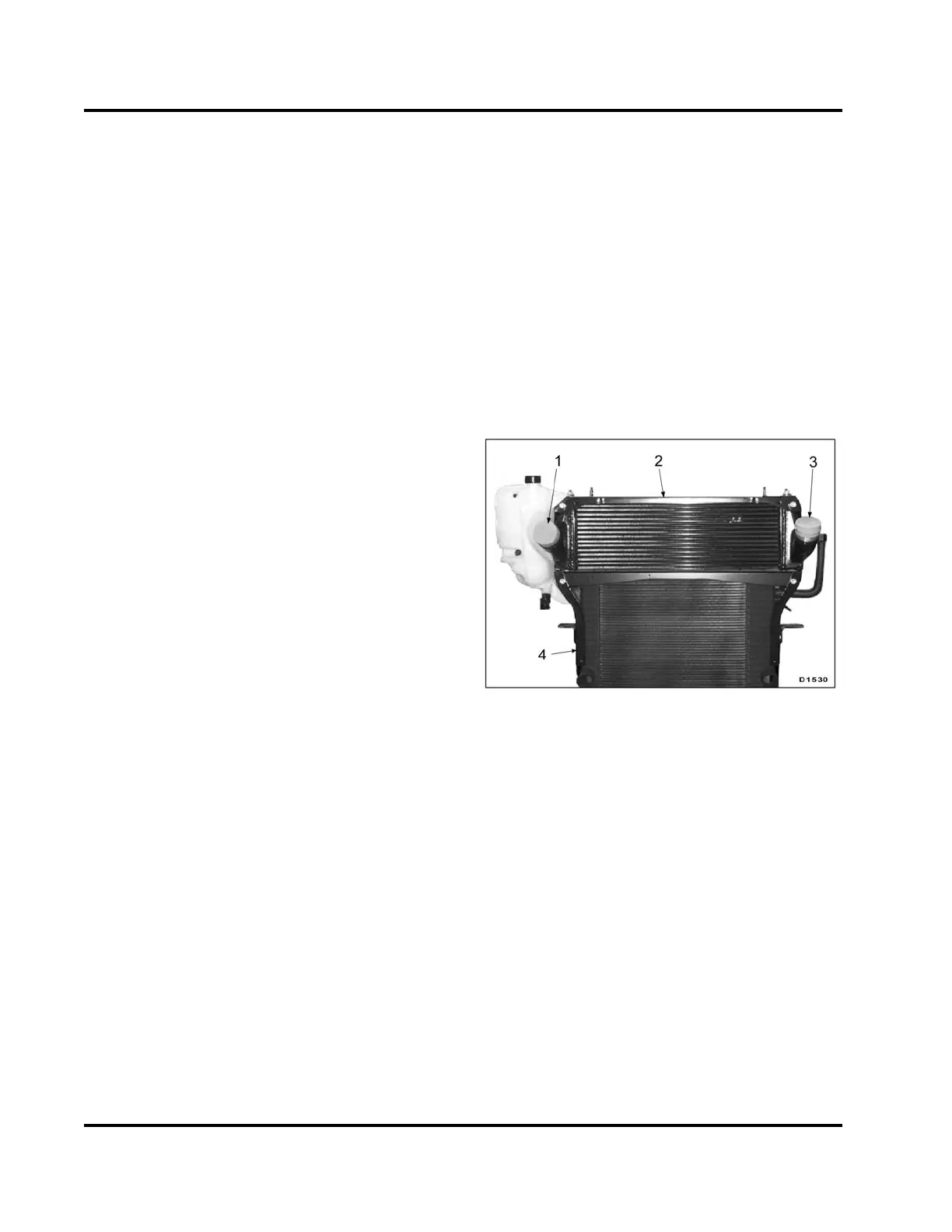
Charge Air C ooler (CAC)
Figure 12 Charge Air Cooler (typical)
1. Air outlet
2. Charge Air Cooler (CAC)
3. Air inlet
4. Radiator
The CAC is mounted on top of the radiator. Air from
the turbocharger passes through a network of heat
exchanger tubes before entering the EGR mixer duct.
Outside air flowing over the tubes and fi ns cools the
charged air. Charged air is cooler and denser than
the uncooled air; cooler and denser air improves
the fuel-to-air ratio during combustion, resulting in
improved emission control and power output.
EGES-265-2
Read all safety instructions in the "Safety Information" section of this manual before doing any procedures.
Follow all warnings, cautions, and notes.
© 2009 Navistar, Inc.
 Loading...


