ENGINE SYSTEMS 29
Fuel Injectors
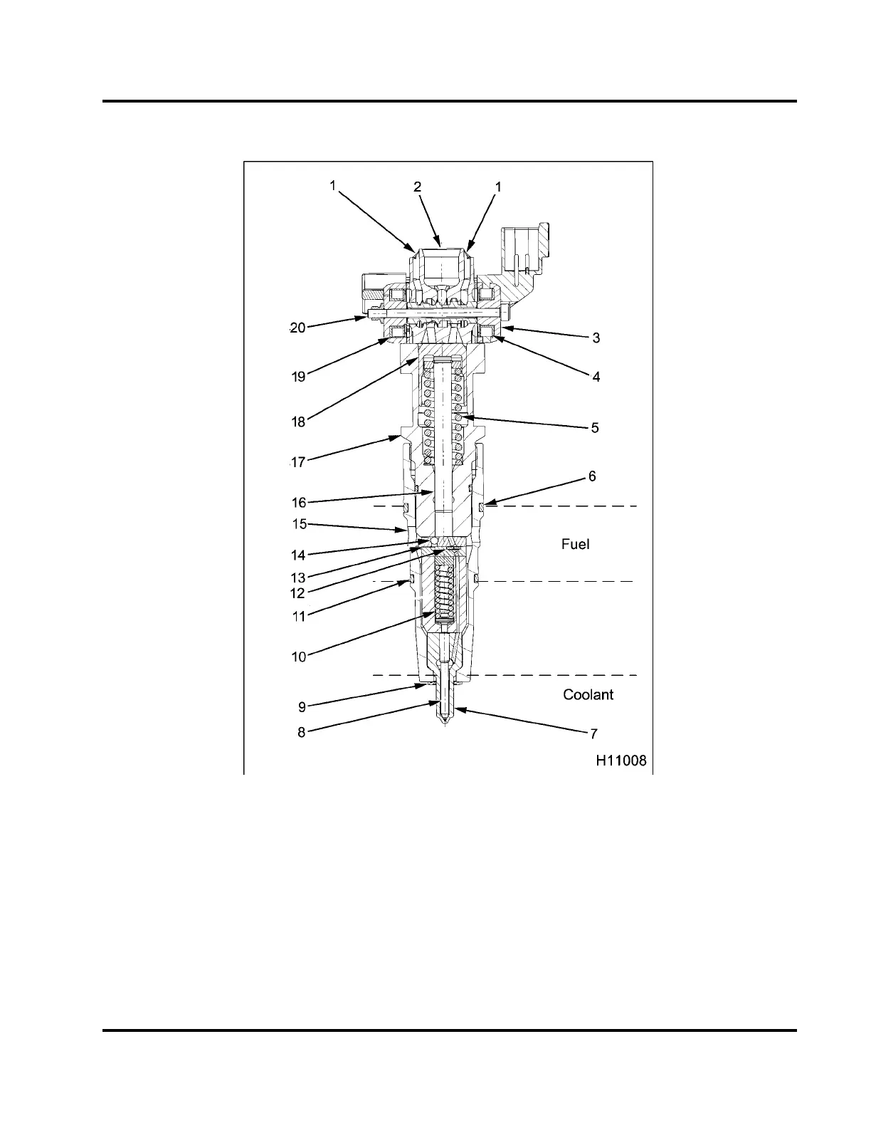
Figure 23 Fuel injector assembly
1. Exhaust port (oil)
2. Inletport(oil)
3. Control valve body
4. OPEN coil
5. Intensifier piston spring
6. Upper O-ring
7. Nozzle assembly
8. Needle
9. Nozzle gasket
10. Valve Opening Pressure (VOP)
spring
11. Lower O-ring
12. Reverse flow check
13. Edge filter
14. Fuel inlet check ball
15. Fuel inlet (4)
16. Plunger
17. Barrel
18. Intensifier piston
19. CLOSE coil
20. Spool valve (control valve)
EGES-265-2
Read all safety instructions in the "Safety Information" section of this manual before doing any procedures.
Follow all warnings, cautions, and notes.
© 2009 Navistar, Inc.
 Loading...


