FRONT COVER AND RELATED COMPONENTS 167
2. Remove four hex fl ange bolts. See fan drive
applications (Table 18).
3. Remove fan hub assembly.
Water Pump Assembly
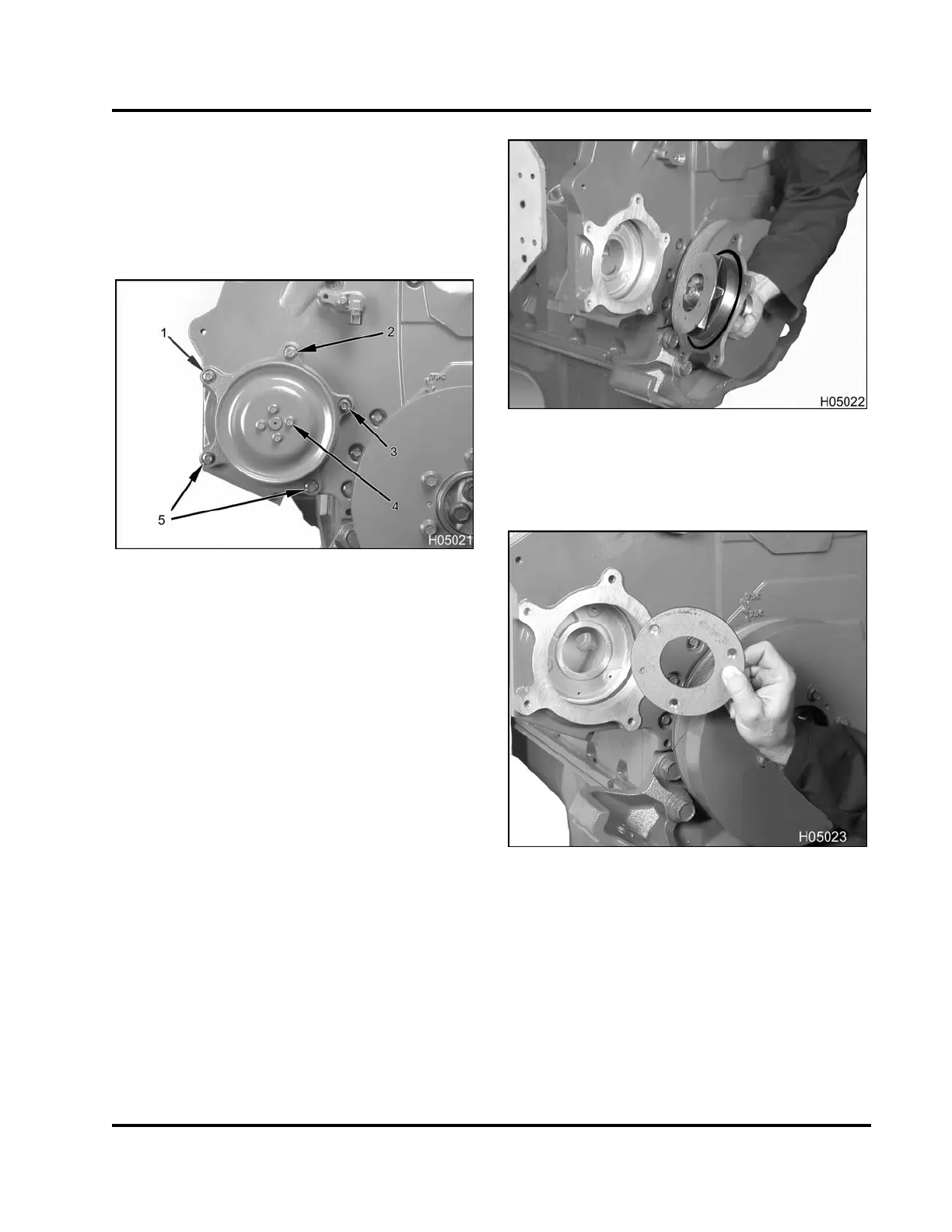
Figure 221 Water pump assembly
1. Bolt,M8x55,nut,M8(1)
2. Bolt, M8 x 100, nut, M8 (1)
3. Bolt, M8 x 16 (1)
4. Bolt, M6 x 12 (4)
5. Bolt, M8 x 40 (2)
1. Remove four pulley bolts (M6 x 12).
2. Remove water pump pulley.
3. Remove one water pump assembly nut (M8) and
bolt (M8 x 55).
4. Remove one water pump assembly nut (M8) and
bolt (M8 x 100).
5. Remove one water pump assembly bolt (M8 x 16).
6. Remove two water pump assembly bolts (M8 x
40).
Figure 222 Water pump assembly
7. Remove water pump assembly. Remove and
discard seal.
Figure 223 Water pump wear plate (Generation
1 front covers only)
8. If applicable, remove three flat head hex socket
screws (M5) securing the water pump wear plate
to the rear half of the front cover and remove water
pump wear plate.
EGES-265-2
Read all safety instructions in the "Safety Information" section of this manual before doing any procedures.
Follow all warnings, cautions, and notes.
© 2009 Navistar, Inc.
 Loading...


