FRONT COVER AND RELATED COMPONENTS 163
DT 570 and HT 570 E ngines Only
Method One – Using a Feeler Gauge
1. Rotate the engine to approximately TDC (Top
Dead Center) compression on No. 1 cylinder (no
valves open). Set the lash on the No. 1 intake
valve to the nominal lash setting of 0.48 mm
(0.019 in).
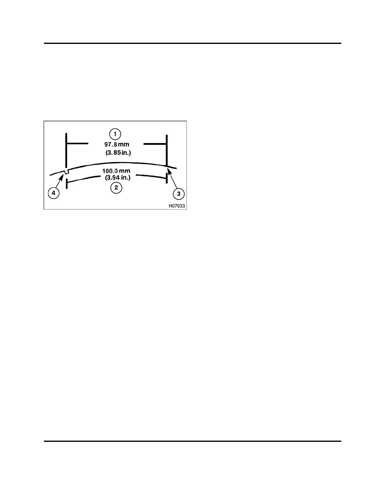
Figure 211 Checking Engine Gear Train Tim
ing
1. Straight line dimension
2. Radial distance dimension
3. Scribe mark
4. Damper timing notch
2. Scribe a mark on the damper pulley at a
radial
distance of 100.0 mm (3.94 in) or a str
aight line
distance of 97.8 mm (3.85 in) clockw
ise from
the timing notch as viewed from the
frontofthe
engine.
3. Place a 0.28 mm (0.011 in) feeler
gauge between
therockerarmandthevalvebri
dge of the No. 1
intake valve. Slowly rotate t
he engine forward
(clockwise) until the intake
valve starts to lift and
the feeler gauge becomes tig
ht. The mark should
lineupwiththeTDCarrowonthefrontcoveror
be within 3.5 crankshaft degrees of it. 3.5 crank
degrees is equivalent to a radial (or straight) line
distance of 8.1 mm (0.32 in) at the damper pulley.
NOTE: One tooth “out of time” on the gear train equals
approximately 11 degrees of movement or 21.4 mm
(27/32 in) of radial distance of damper pulley.
4. If the timing on the No. 1 valve is within
specifications, the other valves, barring extreme
camshaft lobe wear or poor adjustment, will also
be in time. If timing is found to be incorrect,
removal of the front cover is required to inspect
the punch marks on the gear train.
Method Two – Using a Dial Indicator
1. Adjust the No. 1 intake valve with the No. 1 piston
set at TDC (Top Dead Center) compression stroke
to 0.48 mm (0.019 in). Install a 0.28 mm (0.011
in) feeler gauge between the rocker arm and the
valve bridge of the No. 1 intake valve.
2. Position the magnetic base dial indicator on the
valve cover fence of the cylinder head rail with the
indicator tip on the No. 1 intake rocker arm tip.
3. Zero the dial indicator.
4. Rotate the engine approximately one full
revolution in either direction to a position 360
degrees from starting point.
5. The dial indicator should read within the range of
0.13-0.25 mm (0.005-0.010 in) from the starting
position for proper gear train timing.
6. If dial indicator readings are found to be outside of
this range, removal of the front cover is required
to inspect the punch marks on the gear train.
EGES-265-2
Read all safety instructions in the "Safety Information" section of this manual before doing any procedures.
Follow all warnings, cautions, and notes.
© 2009 Navistar, Inc.
 Loading...


