162 FRONT COVER AND RELAT ED COMPONENTS
Checking Gear Train Timing
without Removing Front Cover
Valve train failures from broken or bent push rods,
valves, rocker arms and worn valve keepers and/or
rotators in many instances could be caused by
improper timing of the gear train. Depending on valve
lash setting, if the camshaft gear is improperly timed
by one tooth early, the engine pistons will strike the
intake valve heads or if the timing is set one tooth
late, the exhaust valves may contact pistons.
NOTE: Before attempting to check gear train timing,
it will be necessary to remove the valve cover, valve
cover gasket, and high-pressure oil manifold or
Diamond Logic® engine brake. See the appropriate
sections of this manual regarding removal and
installation procedures.
DT 466 Eng i ne s Onl y
Method On e – Using a Feeler G a uge
1. RotatetheenginetoapproximatelyTDC(Top
Dead Center) compression on No. 1 cylind
er (no
valves open). Set the lash on the No. 1 in
take
valve to the nominal lash setting of 0.
48 mm
(0.019 in).
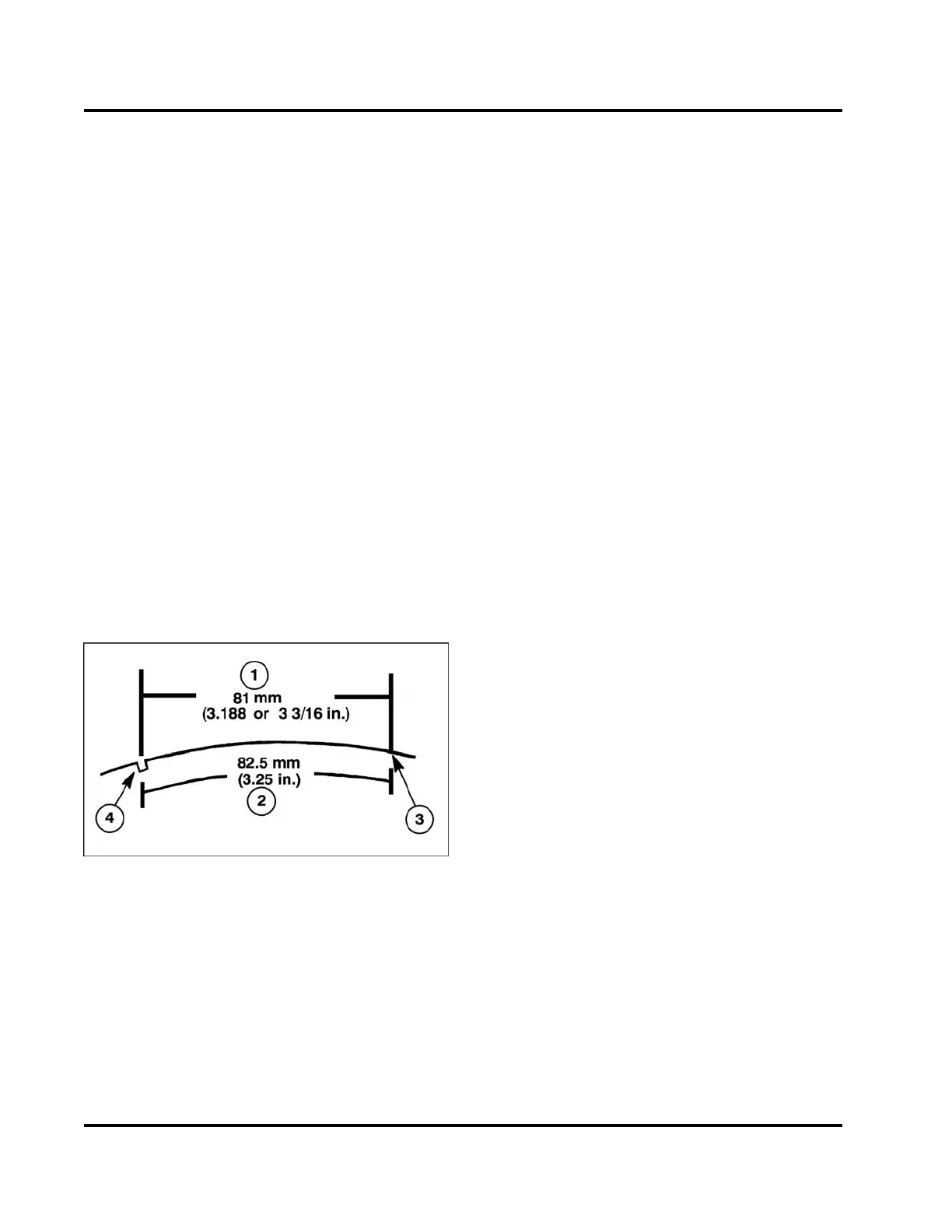
Figure 210 Checking Engine Gear Train Timing
1. Straight line dimension
2. Radial distance dimension
3. Scribe mark
4. Damper timing notch
2. Scribe a mark on the damper pulley at a radial
distance of 82.5 mm (3.25 in) or a straight line
distance of 81 mm (3.188 in) clockwise from
the timing notch as viewed from the front of the
engine.
3. Place a 0.28 mm (0.011 in) feeler gauge between
therockerarmandthevalvebridgeoftheNo. 1
intake valve. Slowly rotate the engine forward
(clockwise) until the intake valve starts to lift and
the feeler gauge becomes tight. The mark should
line up with the TDC arrow on the front cover or be
within 3.5 crankshaft degrees of it. 3.5 degrees is
equivalent to a radial (or straight) line distance of
6.8 mm (0.27 in) at the damper pulley.
NOTE: One tooth “out of time” on the gear train equals
approximately 11 degrees of movement or 21.4 mm
(27/32 in) of radial distance of damper pulley.
4. If the timing on the No. 1 valve is within
specifications, the other valves, barring extreme
camshaft lobe wear or poor adjustment, will also
beintime. Iftimingisfoundtobeincorrect,
removal of the front cover is required to inspect
the punch marks on the gear train.
Method Two – Using a Dial Indicator
1. Adjust the No. 1 intake valve with the No. 1 piston
set at TDC (Top Dead Center) compression stroke
to 0.48 mm (0.019 in). Install a 0.28 mm (0.011
in) feeler gauge between the rocker arm and the
valve bridge of the No. 1 intake valve.
2. Position the magnetic base dial indicator on the
valve cover fence of the cylinder head rail with the
indicator tip on the No. 1 intake rocker arm tip.
3. Zero the dial indicator.
4. Rotate the engine approximately one full
revolution in either direction to a position 360
degrees from starting point.
5. The dial indicator should read within the range of
0.13-0.25 mm (0.005-0.010 in) from the starting
position for proper gear train timing.
6. If dial indicator readings are found to be outside of
this range, removal of the front cover is required
to inspect the punch marks on the gear train.
EGES-265-2
Read all safety instructions in the "Safety Information" section of this manual before doing any procedures.
Follow all warnings, cautions, and notes.
© 2009 Navistar, Inc.
 Loading...


