242 POWER CYLINDERS
CAUTION: To prevent engine damage, use
permanent marker to identify internal engine
components and their orientation. Do not use paint
or temporary markers.
2. Using a permanent marker, mark each connecting
rod bolt and put another mark on a 15 mm 12 point
socket directly in line with the mark on each rod
bolt.
3. Mark the surface of the connecting rod cap 90°
clockwisefromeachmarkontherodbolt.
4. Align mark on socket with mark on the rod bolt and
install socket on the rod bolt.
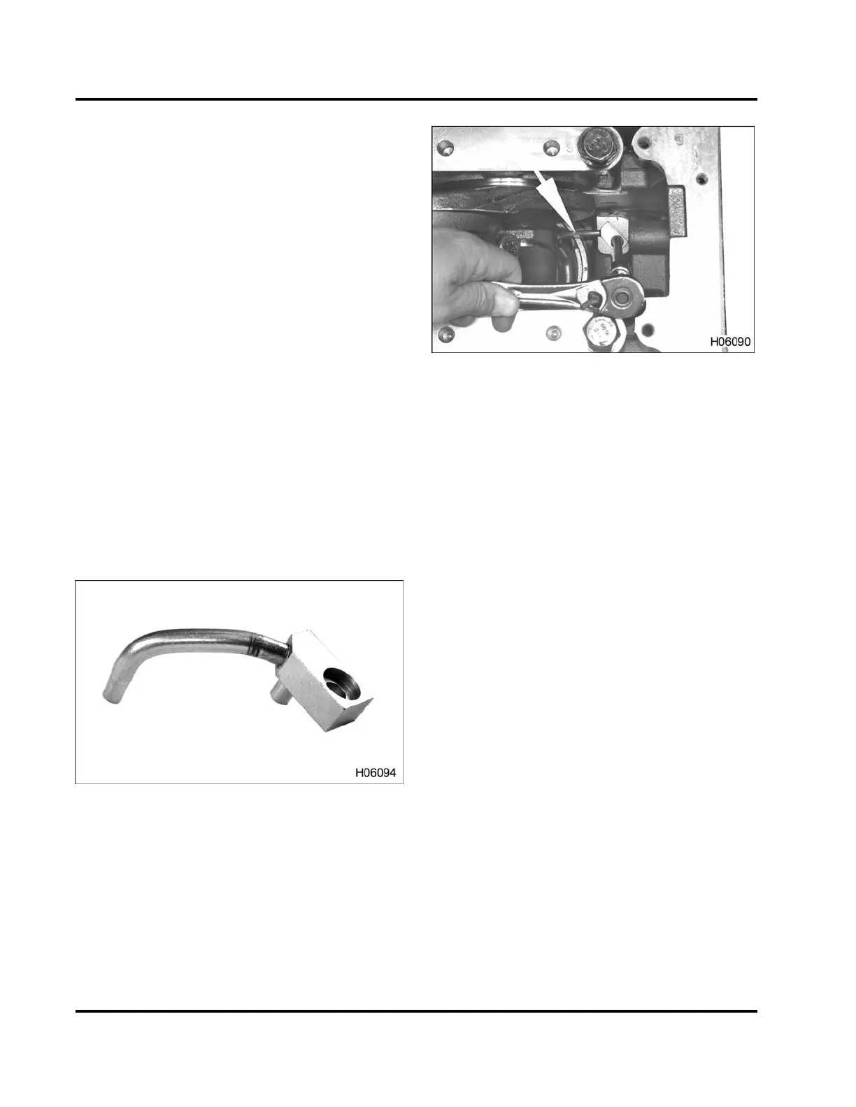
5. Torque-to-yield each M11 connecting rod cap bolt
by rotating bolt exactly 90 degrees clockwise (1/4
turn). The mark on the socket and bolt should
be aligned with the mark on the surface of the
connecting rod cap.
Piston Cooling Tubes
Old Piston C ooling Tu bes
NOTE: The crankshaft may need to be rotated to
access some piston cooling tubes.
Figure 354 Old piston cooling tube
Figure 355 Old piston cooling tube
CAUTION: To prevent engine damage, the piston
cooling tubes use a special patch type mounting bolt.
Do not substitute.
NOTE: Piston cooling tubes are self aligning.
1. Place piston cooling tubes onto crankcase
mounting pad.
2. When installing the piston cooling tube bolts (M6
x 16), do A or B below:
A. Install new piston cooling tube mounting
bolts (patch type).
B. Remove oil residue, and apply Loctite®
#242 to the threads of existing piston
cooling tube mounting bolts (patch type),
and install M6 x 16 bolts.
3. Tighten M6 x 16 bolts to the special torque value
(Table 33).
New Piston Cooling Tubes
NOTE: The crankshaft may need to be rotated to
access some piston cooling tubes.
CAUTION: To prevent engine damage, the correct
piston cooling tubes must be installed.
NOTE: The non-knurled piston cooling tube is
required for DT 466 engines. The knurled piston
cooling tube is required for DT 570 and HT 570
engines.
EGES-265-2
Read all safety instructions in the "Safety Information" section of this manual before doing any procedures.
Follow all warnings, cautions, and notes.
© 2009 Navistar, Inc.
 Loading...


