290 OIL SYSTEM MODULE ASSEMBLY AND SECONDARY FILTRATION
Cleaning and Inspection
Cleaning the Oil System Module
CAUTION: To prevent engine damage, the oil cooler
must be replaced if there was a bearing failure. Debris
from a bearing failure cannot be removed from the oil
cooler.
CAUTION: To prevent engine damage, do not attempt
to clean the assembled oil system module in solvent.
Solvent will be trapped in the oil cooler, regulator valve
assembly, and oil thermal valve assembly. Failure to
follow this caution could result in engine damage.
The following items should be removed:
• Oil cooler
• Regulator valve assembly
• Oil thermal valve assembly
The oil system module housing and lube adapter can
be cleaned in solvent and blown dry with clean filtered
compressed air.
1. Immerse the disassembled oil cooler housing and
lube adapter into a suitable solvent.
WARNING: To prevent personal injury or
death, wear safety glasses with side shiel
ds.
Limit compressed air pressure to 207 k
Pa (30 psi).
2. Flush and drain the oil cooler housing
and
lube adapter to remove any residue. Dr
yall
components with filtered compressed
air.
3. Check the oil cooler housing for bloc
ked orifices
and damaged threads. Replace oil
cooler housing
if required.
4. Remove any debris that may be bloc
king the filter
bypass valve.
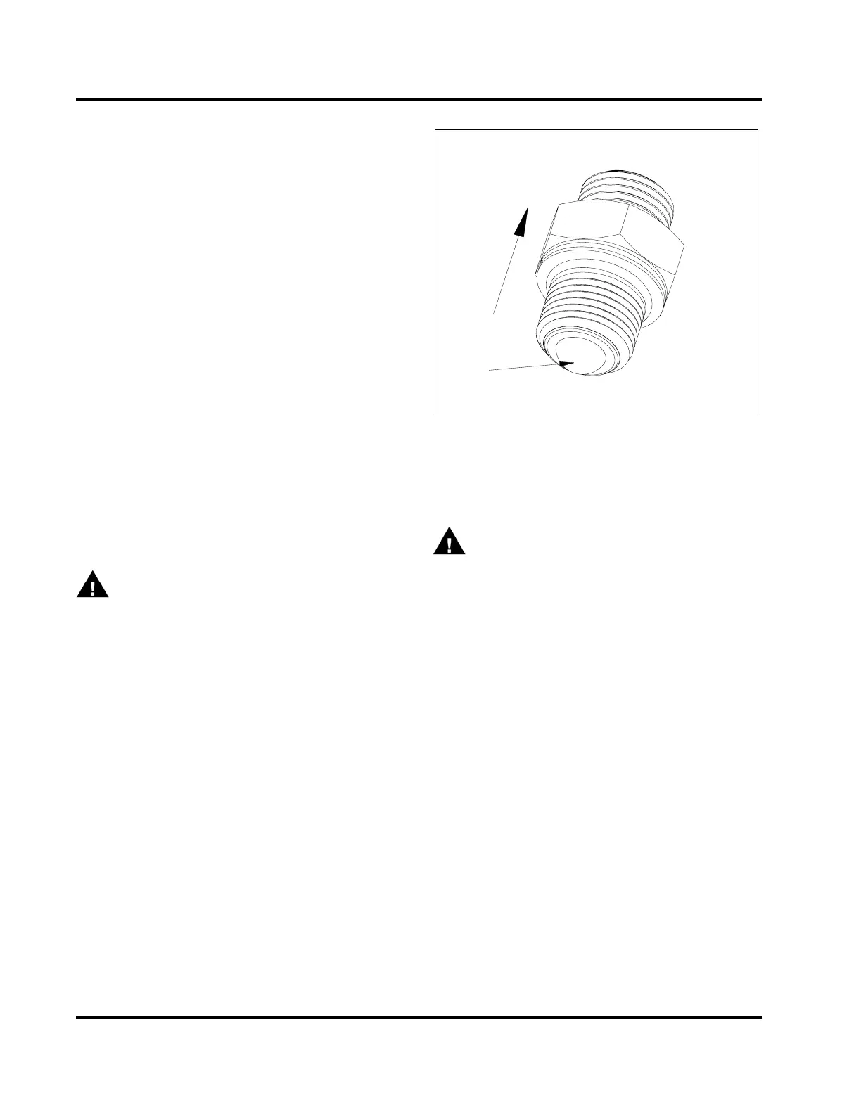
5. Remove turbocharger oil supply fi
tting (M18) on
top of oil filter header and disca
rd O-ring seal.
1
H13031
2
Figure 422 Oil supply tube fitting
1. Direction of oil flow
2. Oil supply wire mesh screen
WARNING: To prevent personal injury or
death, wear safety glasses with side shields.
Limit compressed air pressure to 207 kPa (30 psi).
6. Inspect screen for damage or particle obstruction.
Clean or replace oil supply tube fitting screen as
necessary.
7. Install a new O-ring onto fitting and thread into oil
filter header. Tighten to the special torque value
(Table 42).
Checking the Cooler Heat Exchanger for Leakage
External
CAUTION: To prevent engine damage, do not allow
water to enter oil side of cooler heat exchanger
assembly.
1. Remove the eight bolts (M8 x 20) securing cooler
heat exchanger to the oil system module, if not
done so already.
2. Fasten Oil Cooler Test Plate (Table 43) to cooler
heat exchanger.
3. Make sure oil port valve is closed.
EGES-265-2
Read all safety instructions in the "Safety Information" section of this manual before doing any procedures.
Follow all warnings, cautions, and notes.
© 2009 Navistar, Inc.
 Loading...


