FRONT COVER AND RELATED COMPONENTS 187
Front Engine Mount
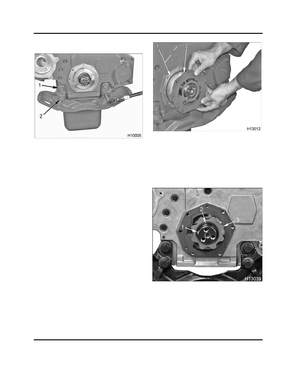
Figure 254 Front engine mount
1. Bolt, M18 x 70 (2)
2. Bolt, M18 x 100 (2)
1. Position front engine mount onto front cover
assembly.
2. Install two upper bolts (M18 x 70) finger tight.
3. Install two lower bolts (M18 x 100) finger tight.
4. Tighten all four bolts to the special torque value
(Table 20) .
Gerotor Oil Pump Assembly and Front Oil Seal
Up to late Model Year 2006, all International® DT 466,
DT 570 and HT 570 Diesel Engines were equipped
with an 8 lobe gerotor oil pump.
Later in Model Year 2006, International® DT 466 (210
to 245 horsepower) Diesel Engines were equipped
with a 10 lobe gerotor oil pump.
NOTE: Installation procedures for the gerotor oil
pump assembly show the 8 lobe gerotor oil pump.
Installation procedures for the 10 lobe gerotor oil
pump are the same as for the 8 lobe gerotor oil pump.
1. If removed, install new oil pump drive (spline) onto
the crankshaft, (Crankshaft Assembly, page268).
Figure 255 Oil pump housing plate and seal
1. Oil pump (housing plate) seal
2. Oil pump housing plate
2. Place oil pump (housing plate) seal int
ofront
cover recess. Align oil pump housing p
late with
dowels.
Figure 256 Vibration damper key, washer seal,
and inner rotor
1. Vibration damper key
2. Washer seal
3. Inner rotor
EGES-265-2
Read all safety instructions in the "Safety Information" section of this manual before doing any procedures.
Follow all warnings, cautions, and notes.
© 2009 Navistar, Inc.
 Loading...


