FRONT COVER AND RELATED COMPONENTS 199
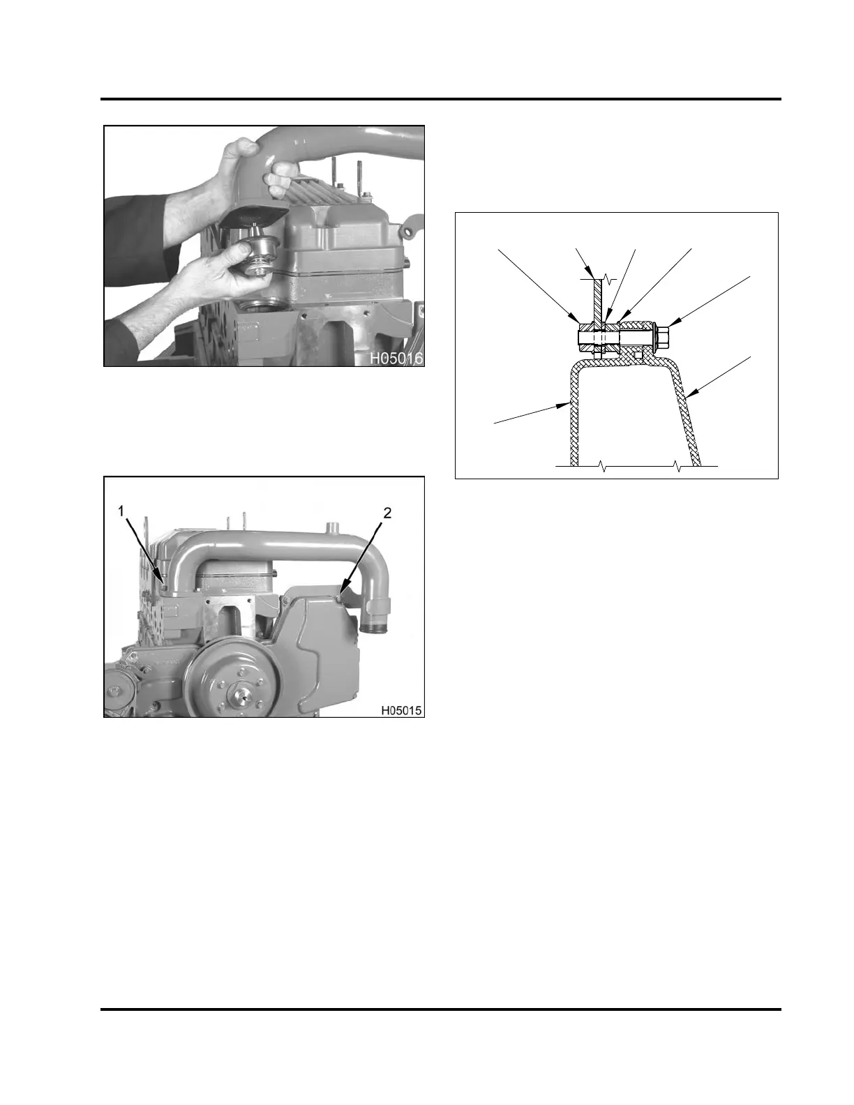
Figure 280 Thermostat assembly
4. Install a new thermostat and gasket into cylinder
head.
Figure 281 Water outlet tube assembly
1. Bolt, M8 x 25 (2)
5. Install water outlet tube assembly and secure with
two water outlet tube assembly bolts (M8 x 25) at
the cylinder head. Tighten to the special torque
value (Table 20) .
1
2
3
4
6
H05029
2
5
Figure 282 Water outlet tube assem
bly
connection at front cover
1. Front cover (front half)
2. Hex flange nut, M8 (4)
3. Water outlet tube assembly (bracke
t)
4. Washer (2)
5. Hex flange bolt, M8 x 40 (2)
6. Front cover (rear half)
6. Install nuts, bolts and washers to
secure the water
outlet tube assembly at the front
cover. Tighten
nuts and bolts to the special torq
ue value (Table
20).
EGES-265-2
Read all safety instructions in the "Safety Information" section of this manual before doing any procedures.
Follow all warnings, cautions, and notes.
© 2009 Navistar, Inc.
 Loading...


