CYLINDER HEAD AND VALVE TRAIN 151
Chart 1
Valve and brake lash adjustments (inches) with piston 1 at TDC compression (Chart 1)
Cylinder 1 Cylinder 2 Cylinder 3 Cylinder 4 Cylinder 5 Cylinder 6
intake
1
exhaust
2
intake
3
exhaust
4
intake
5
exhaust
6
intake
7
exhaust
8
intake
9
exhaust
10
intake
11
exhaust
12
0.019 0.019 0.019 0.019 0.019 0.019
Brake 0.019 Brake 0.019 Brake 0.019
Valve and brake lash adjustments with piston 1 at TDC compression
Chart 2
Valve and brake lash adjustments (inches) with piston 6 at TDC compression (Chart 2)
Cylinder 1 Cylinder 2 Cylinder 3 Cylinder 4 Cylinder 5 Cylinder 6
intake
1
exhaust
2
intake
3
exhaust
4
intake
5
exhaust
6
intake
7
exhaust
8
intake
9
exhaust
10
intake
11
exhaust
12
0.019 0.019 0.019 0.019 0.019 0.019
Brake 0.019 Brake 0.019 Brake 0.019
Valve and brake lash adjustment s with piston 6 at TDC c
ompression
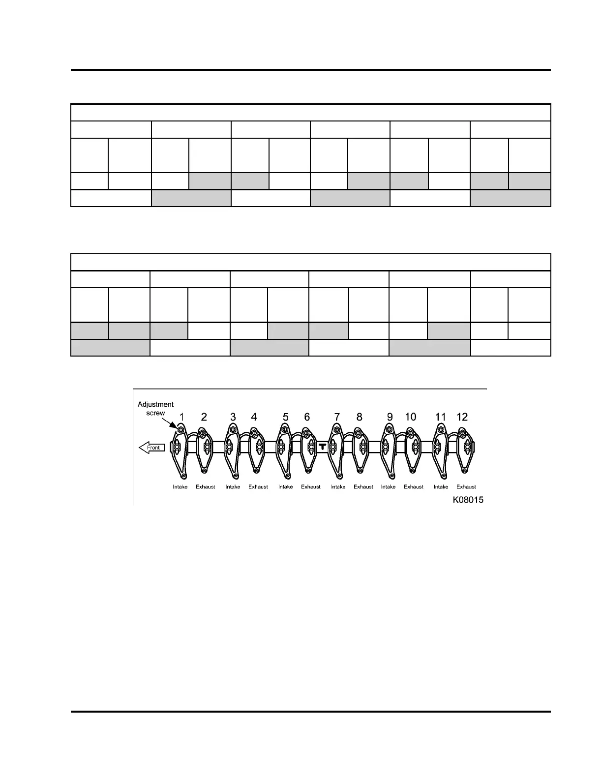
Figure 206 Valve lash adjustment
EGES-265-2
Read all safety instructions in the "Safety Information" section of this manual before doing any procedures.
Follow all warnings, cautions, and notes.
© 2009 Navistar, Inc.
 Loading...


