CYLINDER HEAD AND VALVE TRAIN 153
1
1
1
1
3
2
4
H08100
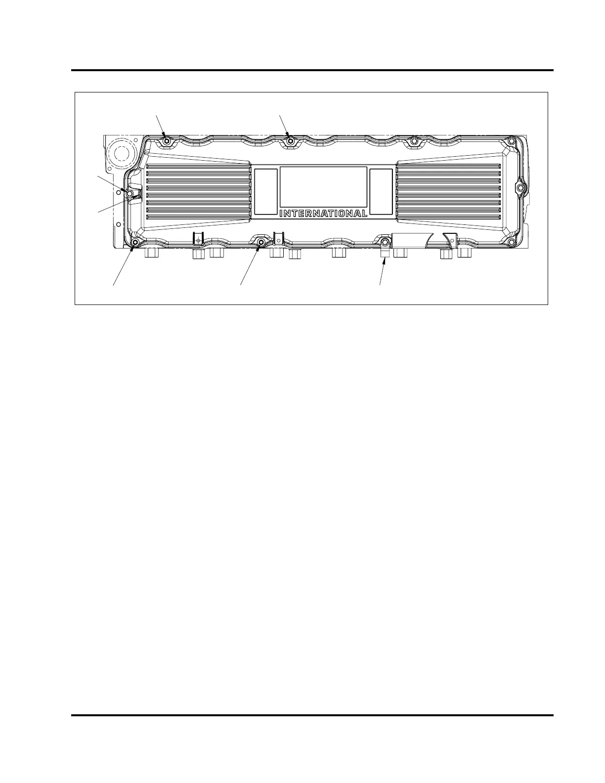
Figure 208 Valve cover assembly detail
1. Bolt / stud, M8 x 80 / 19 (4)
2. Extension bracket
3. Valve cover harness mounting
bracket
4. Bolt, M8 x 80 (6)
4. Install four valve cover bolt / studs (M8 x 80 / 19)
finger tight.
5. Install six valve cover bolts (M8 x 80) finger tight.
6. Tighten all bolts and studs to the standard torque
value (General Torque Guidelines, page445).
7. Add any necessary brackets to the appropriate
studs.
8. Connect crankcase ventilation piping (Crankcase
Ventilation System, page274).
9. Add coolant (if cylinder head was removed in
chassis).
EGES-265-2
Read all safety instructions in the "Safety Information" section of this manual before doing any procedures.
Follow all warnings, cautions, and notes.
© 2009 Navistar, Inc.
 Loading...


