16 ENGINE SYSTEMS
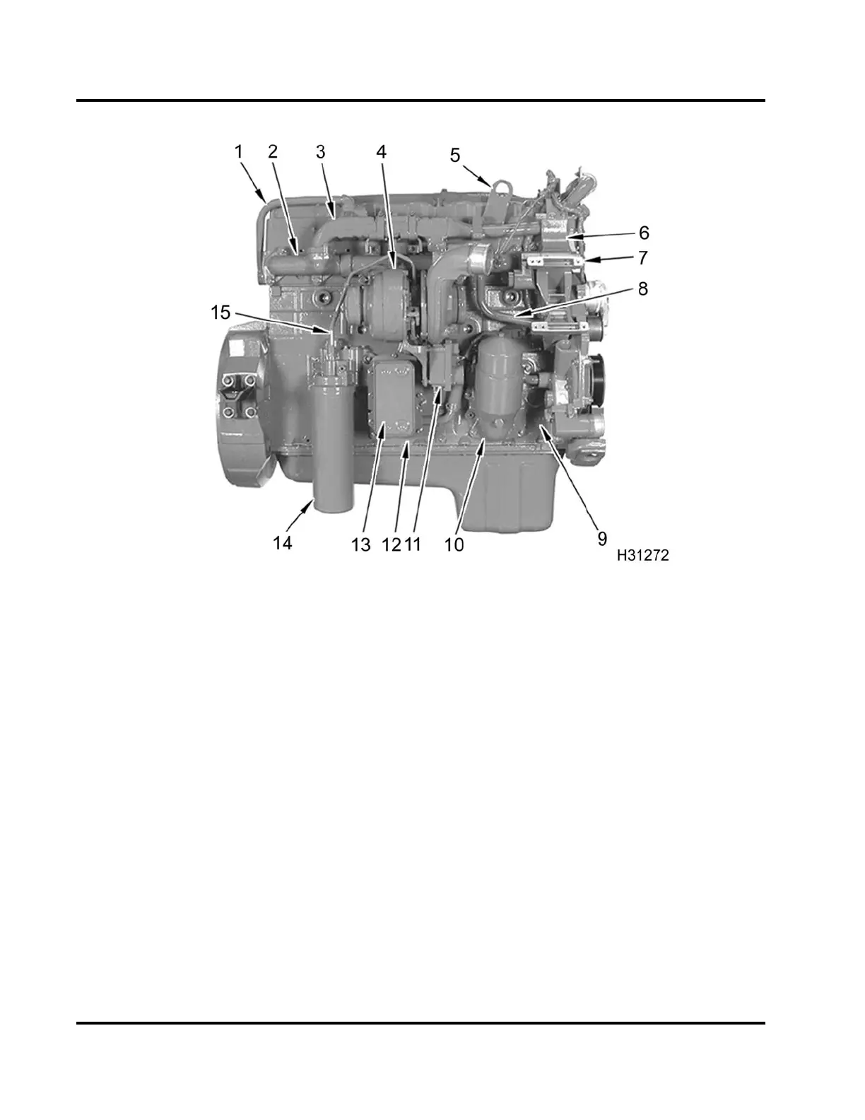
Figure 8 Component location – right
1. EGR cooler return tube
assembly
2. Exhaust manifold assembly
3. EGR cooler assembly
4. Variable Geometry Turbocharger
(VGT)
5. Engine lifting eye
6. Water supply housing (Freon®
compressor bracket)
7. Alternator bracket
8. EGR cooler supply tube
assembly
9. Crankcase
10. Secondary filtration filter
(optional)
11. Turbocharger control module
12. Coolant drain plug (underneath
location)
13. Oil cooler
14. Oil filter
15. Turbo oil inlet tube (supply)
EGES-265-2
Read all safety instructions in the "Safety Information" section of this manual before doing any procedures.
Follow all warnings, cautions, and notes.
© 2009 Navistar, Inc.
 Loading...


