POWER CYLINDERS 233
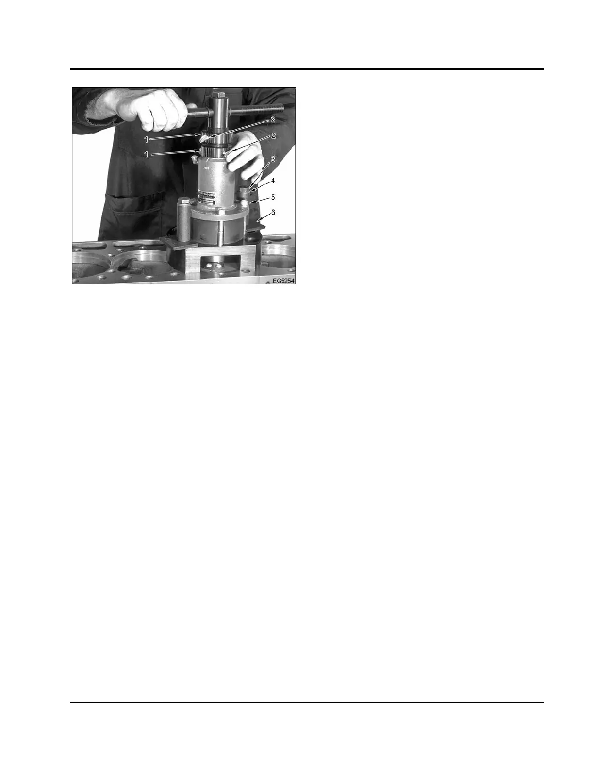
Figure 333 Positioning counterboring tool
1. Turn knuckles
2. Locking screws
3. Mounting bolt (2)
4. Washer (2)
5. Spacer (2)
6. Locking plate (2)
3. Pull the plunger and lift up on the handle to raise
the cutting head. Mount the counterboring tool on
the crankcase. Install the washers and mounting
bolts finger tight, then tighten the bolts to 45 N·m
(33 lbf·ft).
4. To lower the cutting head, loosen the locking
screws and the turn knuckles. Pull the plunger up
to the desired height. Tighten the turn knuckles
and locking screws.
NOTE: Do not remove more than 0.05 mm (0.002 in)
of material at any one attempt.
5. To set the depth of the cut, use one of the following
methods:
Graduated Marks on Tool
a. Loosen the locking screw and turn the
adjusting nut counterclockwise until it
contacts the housing of the driver unit.
b. Back off the adjusting nut by the amount
of the desired cut. Each graduated mark
equals 0.03 mm (0.001 in).
c. Tighten the locking screw.
Feeler Gauge
a. Loosen the locking screw on the upper
turn knuckle and insert the correct size of
feeler gauge between the turn knuckles.
b. Rotate the upper turn knuckle until the
feeler gauge is barely held between the
turn knuckles.
c. Tighten the locking screw and remove the
feeler gauge.
CAUTION: To prevent engine damage, do not rotate
the handle counterclockwise when the tool bit is in
contact with the counterbore ledge as damage to the
tool bit could result as well.
6. To cut the counterbore, rotate the handle smoothly
in a clockwise direction until the driver unit turns
freely and is bottomed out between the adjusting
nut and the top of the driver unit housing.
7. Remove the counterboring tool and clean the
counterbore area. Check the depth of the
counterbore (Checking Counterbore Depth, page
229).
EGES-265-2
Read all safety instructions in the "Safety Information" section of this manual before doing any procedures.
Follow all warnings, cautions, and notes.
© 2009 Navistar, Inc.
 Loading...


