236 POWER CYLINDERS
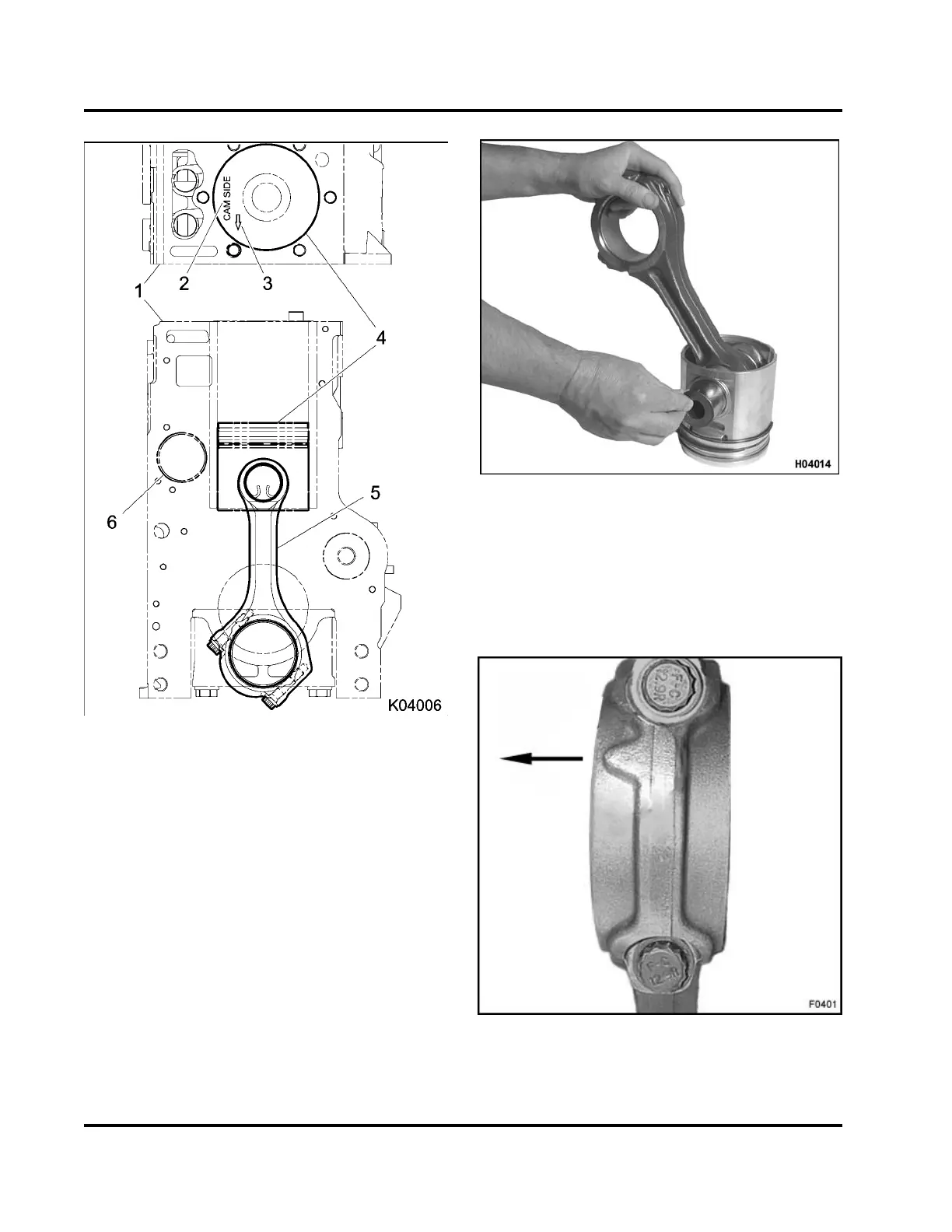
Figure 339 Piston and connecting rod
orientation
1. Crankcase
2. CAM SIDE stamp
3. Arrow stamp
4. Piston
5. Connecting rod
6. Camshaft bore
NOTE: One piece pistons are stamped CAM SIDE or
with an arrow.
• Install piston with CAM SIDE over short leg of the
connecting rod.
• Install piston with arrow stamp (on left side of
piston) over short leg of the connecting rod.
Figure 34 0 Installing piston pin
CAUTION: To prevent engine damage, do not mix
connecting rods with M12 bolts and connecting rods
with M11 bolts in the same engine. If one or more
connecting rods must be replaced make sure all
connecting rods in each engine are the same type.
Figure 341 Connecting rod cap w ith M12
connecting rod cap bolts (protrusion points to
front of engine)
EGES-265-2
Read all safety instructions in the "Safety Information" section of this manual before doing any procedures.
Follow all warnings, cautions, and notes.
© 2009 Navistar, Inc.
 Loading...


