254 CRANKCASE, C RAN KSHAFT, AND CAMSHAFT
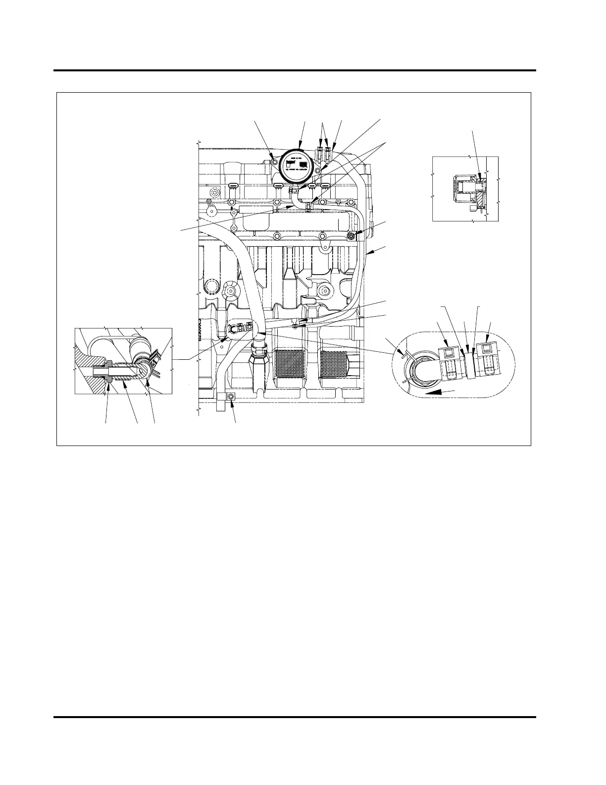
Black side
Gray side
Flow
direction
H17017
1
2
3
4
5
6
7
8
5
9
9
9
10
4
9
11
12
13
14
Side View
Breather assembly
Side view
15
Figure 360 Crankcase ventilation system
1. Breather assembly
2. Clamp, 25.4 mm (1 in) diameter
(2)
3. Hose,25.4mm(1in)I.D.
4. Bolt, M8 x 35 (2)
5. Clamp, 1/2 in. diameter (3)
6. Nut, M10
7. Vent and drain tube assembly
8. Reducer hose
9. Clamp (3)
10. Check valve
11. Bolt, M8 x 16
12. Rubber elbow
13. Fitting assembly, M12
14. Drain hose elbow
15. O-ring, #214
NOTE: Have an oil pan handy before disconnecting
the oil drain hose. It is possible for a column of oil to
be maintained above the check valve, as the check
valve does require a certain amount of pressure to
allow passage of oil back to the crankcase.
To remove the crankcase ventilation system as an
assembled unit, do the following steps.
1. Move clamp (1/2 in) out of way and remove
reducer hose from vent and drain tube assembly.
Allow tube and reducer hose to drain. Reconnect
reducer hose and clamp.
2. Remove clamp and rubber elbow on the
crankcase side of the check valve. Leave fitting
assembly in crankcase unless evidence of leaking
is occurring from fitting O-ring.
3. Remove the bolt (M8 x 16) securing the vent and
drain tube assembly to the crankcase, located at
the end of the vent tube.
4. Remove two bolts (M8 x 35) securing the breather
assembly to the valve cover.
EGES-265-2
Read all safety instructions in the "Safety Information" section of this manual before doing any procedures.
Follow all warnings, cautions, and notes.
© 2009 Navistar, Inc.
 Loading...


