CRANKCASE, CRANKSHAFT, AND CAMSHAFT 275
Black side
Gray side
Flow
direction
H17017
1
2
3
4
5
6
7
8
5
9
9
9
10
4
9
11
12
13
14
Side View
Breather assembly
Side view
15
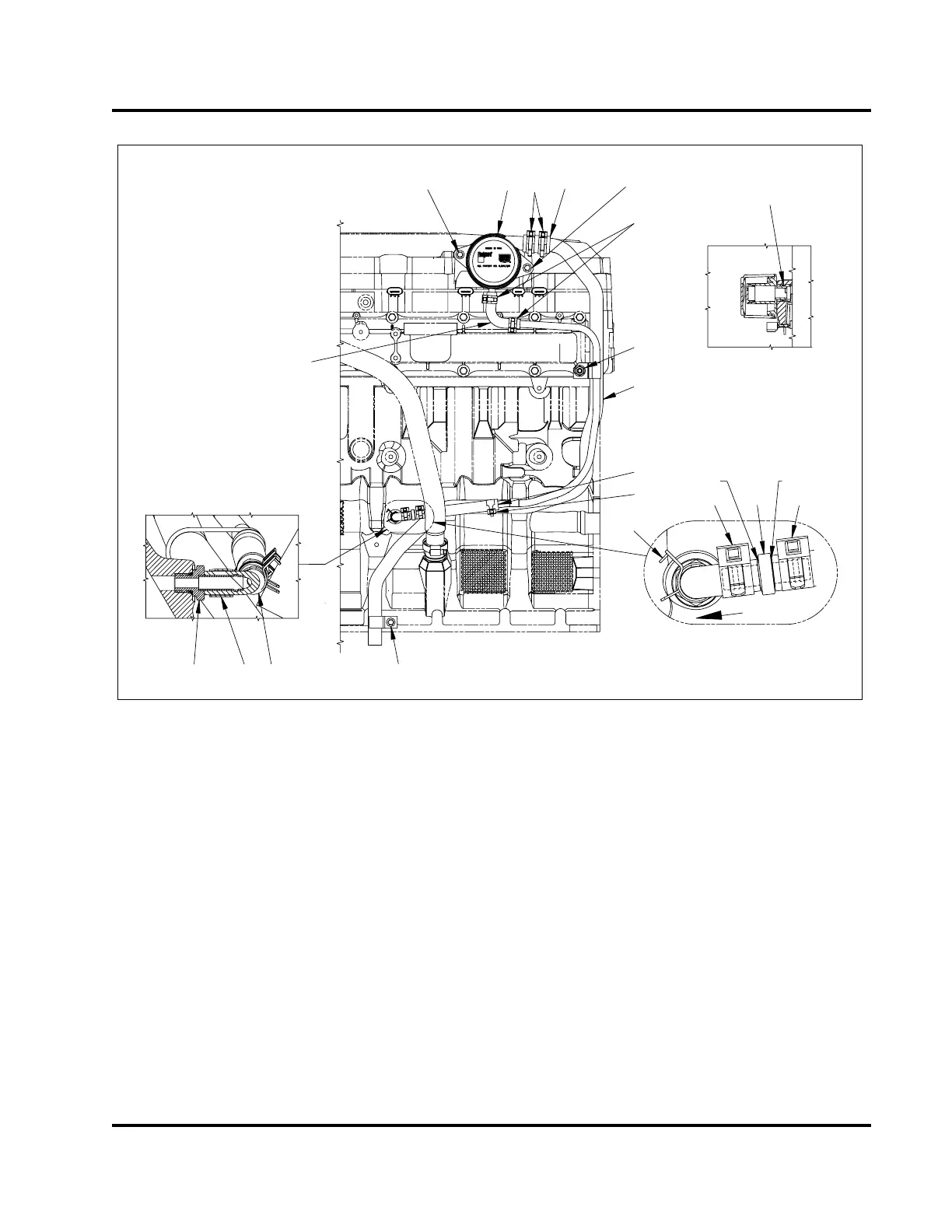
Figure 403 Crankcase ventilation
1. Breather assembly
2. Clamp, (1 in) diameter (2)
3. Hose, (1 in) I.D.
4. Bolt, M8 x 35 (2)
5. Clamp, 1/2 in diameter (3)
6. Nut, M10
7. Vent and drain tube assembly
8. Reducer hose
9. Clamp (3)
10. Check valve
11. Bolt, M8 x 16
12. Rubber elbow
13. Fitting assembly, M12
14. Drain hose elbow
15. O-ring, #214
3. Position drain hose elbow and one inch hose
onto breather assembly. Secure with clamps, see
illustration.
4. Place appropriate hose clamps onto vent and
drain tube assembly. Position vent and drain tube
assembly into breather assembly hoses.
5. Align vent and drain tubing assembly bracket with
intake manifold stud. Thread nut (M10) onto stud
finger tight.
6. Attach bottom of vent tubing to crankcase and
secure with bolt (M8 x 16).
7. Combine rubber elbow, clamps, check valve, and
reducer hose, making sure check valve is oriented
correctly. Connect to drain side of tubing and
clamp.
8. Tighten all hardware to the standard torque value
(General Torque Guidelines, page445)andmove
clamps into their sealing positions.
EGES-265-2
Read all safety instructions in the "Safety Information" section of this manual before doing any procedures.
Follow all warnings, cautions, and notes.
© 2009 Navistar, Inc.
 Loading...


