OIL SYSTEM MODULE A SSE MBLY A ND SECONDARY FILTRATION 281
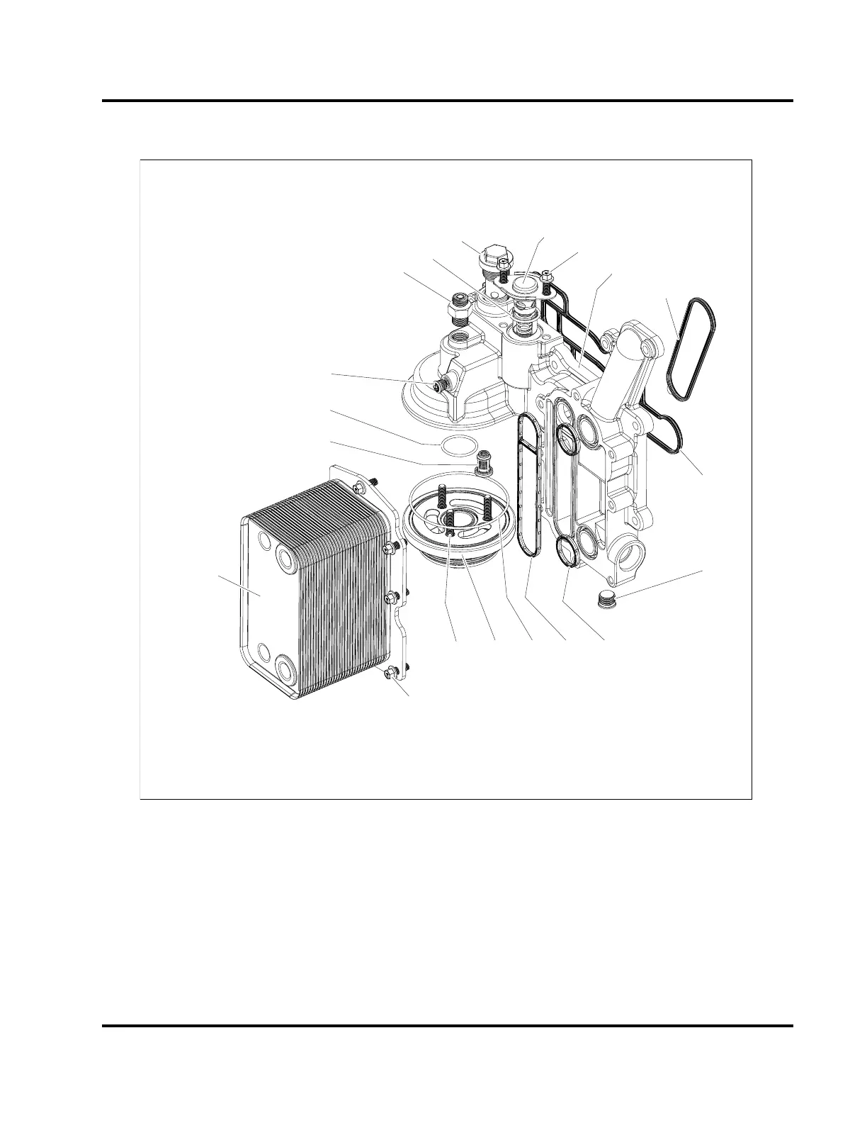
Component Exploded View
H13003
1
2
3
4
5
6
7
8
9
10
11
12
13
14
15
16
17
18
19
Figure 404 Oil system module assembly
1. Oil supply tube fitting and O-ring
2. O-ring gasket
3. Regulator valve assembly
4. Hex flange screw, M8 x 20 (2)
5. Oil thermal valve assembly
6. Oil cooler housing
7. Coolant seal
8. Oil seal
9. Plug assembly, M18 (coolant)
10. Coolant seal (2)
11. Oil seal
12. O-ring gasket
13. Lube adapter (not serviceable)
14. Bolt, M8 x 25 (3)
15. Bolt, M8 x 20 (8)
16. Cooler heat exchanger (23 or 33
plates)
17. Bypass valve
18. O-ring gasket
19. Plug assembly, M12
EGES-265-2
Read all safety instructions in the "Safety Information" section of this manual before doing any procedures.
Follow all warnings, cautions, and notes.
© 2009 Navistar, Inc.
 Loading...


