288 OIL SYSTEM MODULE ASSEMBLY AND SECONDARY FILTRATION
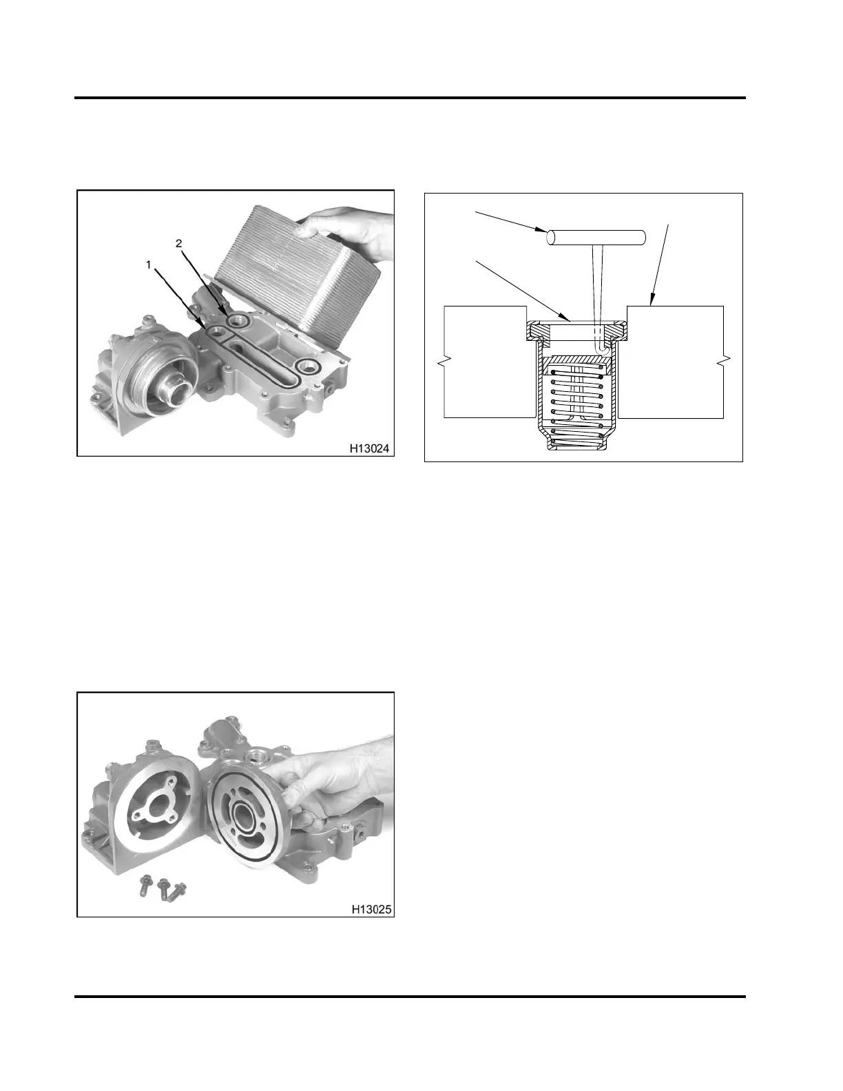
5. Using a small hammer and a piece of wood, apply
just enough force (at large arrow) to break the
coolant and oil gasket bonds.
Figure 417 Oil and coolant seals
1. Oil seal
2. Coolant seal (2)
6. Discard one oil seal two coolant seals.
7. Remove the three bolts (M8 x 25) retaining the
lube adapter to the oil cooler housing.
NOTE: Bolts are thread-forming fasteners. These
bolts may be removed and reinstalled, or may be
replaced with standard machined bolts.
Figure 418 Lube adapter assembly and gaskets
8. Remove the lube adapter to provide access to
the oil bypass valve, which is pressed into the
housing. Discard the two O-ring gaskets.
1
2
3
H13028
Figure 419 Remov ing th e oil byp ass val ve
1. Oil bypass valve
2. Hooked shaped tool (tool size shown not to scale)
3. Oil system module casting
9. Remove the oil bypass valve (only if determined
to be defective) by inserting a hook shaped tool
(make locally) and depressing the check valve,
while catching the valve seat. The use of a Slide
Hammer (Table 43) threaded completely through
valve is an alternative method.
EGES-265-2
Read all safety instructions in the "Safety Information" section of this manual before doing any procedures.
Follow all warnings, cautions, and notes.
© 2009 Navistar, Inc.
 Loading...


