326 ENGINE ELECTRICAL
Sensor harn es s a t ECM, IDM, and EGR drive
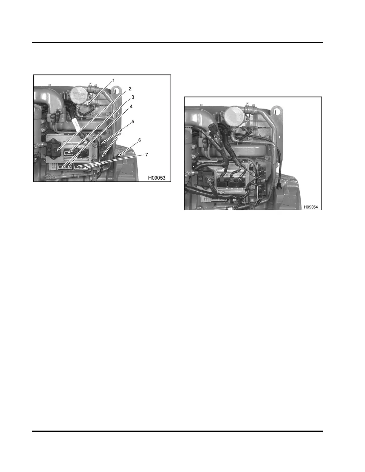
module
Figure 499 Sensor harness locations
1. ICP sensor connector
2. EGR drive module
3. IDM connector
4. ECM chassis connectors (2)
5. Intake air heater relay connections
6. CKP sensor
7. ECM engine connectors (2)
18. Connect two ECM engine connectors.
19. Connect the CKP sensor.
20. Connect two intake air heater relay connectors.
21. Connect two ECM chassis connectors.
22. Connect the IDM connector.
23. Connect the EGR drive module.
24. Connect the ICP connector to the valve cover
gasket.
Figure 500 ECM, IDM, EGR drive module, and
tube assembly overview
25. Install injector wiring harness underneath the
EGR mixer duct and place harness snaps into
anchor locations along the top side of the intake
manifold.
26. Install all wiring harness snaps securing the
sensor and injector wiring harnesses to the
engine.
EGES-265-2
Read all safety instructions in the "Safety Information" section of this manual before doing any procedures.
Follow all warnings, cautions, and notes.
© 2009 Navistar, Inc.
 Loading...


