ENGINE SYSTEMS 31
beneath the plunger. The needle control spring holds
the needle onto its seat to prevent fuel from entering
the combustion chamber.
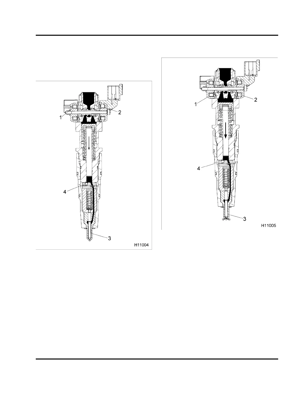
Main inject ion (Step 1 )
Figure 25 Main injection (Step 1)
1. CLOSE coil (off)
2. OPEN coil (on)
3. Needle (seated)
4. Fuel inlet check ball (seated)
A pulse width current energizes the OPEN coil.
Magnetic force moves the spool valve open.
High-pressure oil flows past the spool valve and
onto the top of the intensifier piston. Oil pressure
overcomes the force of the intensifier piston spring
and the intensifier starts to move down. An increase
in fuel pressure under the plunger seats the fuel inlet
check ball, and fuel pressure starts to build on the
needle.
Main injection (Step 2)
Figure 26 Main injection (Step 2)
1. CLOSE coil (off)
2. OPEN coil (off)
3. Needle (unseated – VOP)
4. Fuel inlet check ball (seated)
The pulse-width controlled current to the OPEN coil
is shut off, but the spool valve remains open. High
pressure oil from high pressure oil rail continues to
flow past the spool valve. The intensifier piston and
plunger continue to move and fuel pressure increases
in the barrel. When fuel pressure rises above the VOP
- about 28 MPa (4,075 psi) - the needle lifts of its seat
and injection begins.
EGES-265-2
Read all safety instructions in the "Safety Information" section of this manual before doing any procedures.
Follow all warnings, cautions, and notes.
© 2009 Navistar, Inc.
 Loading...


