38 ENGINE SYSTEMS
Oil Flow Diagram
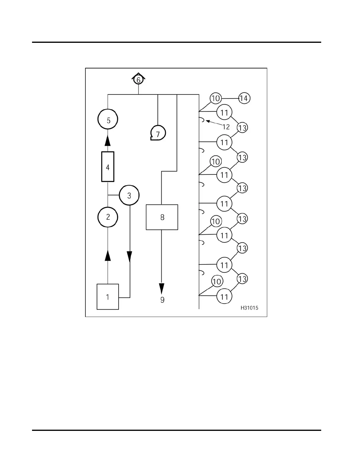
Figure 33 Lubrication system
1. Sump
2. Oil pump
3. Secondary filtration filter
(optional)
4. Oil cooler
5. Oil filter
6. Regulator valve
7. Variable Geometry Turbocharger
(VGT)
8. Oil reservoir for high-pressure
pump
9. To high-pressure oil system
10. Cam bearings
11. Main bearings
12. Piston cooling tubes (6)
13. Connecting rods
14. Rocker arm shaft
The gerotor oil pump, driven by the engine crankshaft,
draws unfiltered oil from the oil pan through an oil
pick-up tube into the inlet port of the front cover.
Unfiltered oil (under pressure) flows through the
outlet port in the front cover into the unfiltered oil
gallery in the crankcase.
The unfiltered oil gallery has one exit port to the
header of the oil cooler. The oil is then internally
EGES-265-2
Read all safety instructions in the "Safety Information" section of this manual before doing any procedures.
Follow all warnings, cautions, and notes.
© 2009 Navistar, Inc.
 Loading...


