52 ENGINE SYSTEMS
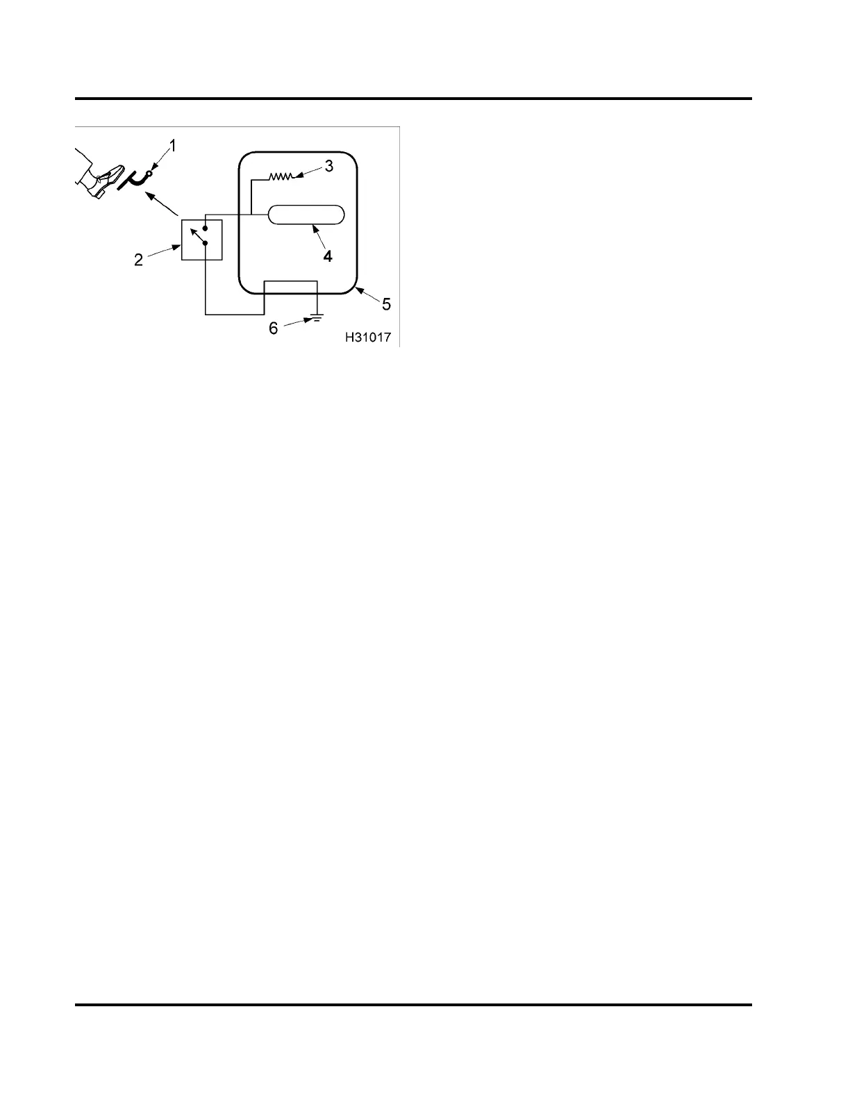
Figure 45 Switch
1. Accelerator pedal
2. Idle Validation Switch (IVS)
3. Voltage source with current limiting resistor
4. Microprocessor
5. ECM
6. Ground
Switches
•DDS
•ECL
•IVS
•WIF
Switch sensors indicate position. They operate open
or closed, allowing or preventing the flow of current.
A switch sensor can be a voltage input switch or a
grounding switch. A voltage input switch supplies the
ECM with a voltage when it is closed. A grounding
switch grounds the circuit when closed, causing a
zero voltage signal. Grounding switches are usually
installed in series with a current limiting resistor.
Driveline Disengagement Switch (DDS)
The DDS determines if a vehicle is in gear. For
manual transmissions, the clutch switch serves as
the DDS. For automatic transmissions, the neutral
indicator switch functions as the DDS.
Engine Coolant Level (ECL)
ECL is part of the Engine Warning Protection System
(EWPS).TheECLswitchisusedinplasticdeaeration
tank. When a magnetic switch is open, the tank is full.
If engine coolant is low, the red ENGINE lamp on the
instrument panel is illuminated.
Idle Validation Sw it ch (IVS)
The IVS is a redundant switch that provides the ECM
with a signal that verifies when the APS is in the idle
position.
Water In Fuel (WIF)
A Water In Fuel (WIF) sensor detects water in the
fuel. When enough water accumulates at the bottom
of the housing, the WIF sensor sends a signal to
the Electronic Control Module (ECM); the ECM sets
a Diagnostic Trouble Code (DTC) and illuminates
theamberWATERINFUELlampontheinstrument
panel. The WIF is installed in the base of the fuel filter
housing.
EGES-265-2
Read all safety instructions in the "Safety Information" section of this manual before doing any procedures.
Follow all warnings, cautions, and notes.
© 2009 Navistar, Inc.
 Loading...


