88 INTAKE, INLET, AND EXHAUST M ANIF OLDS
1
23
4
5
6
7
8
9
10 11
12
13
14
H14025
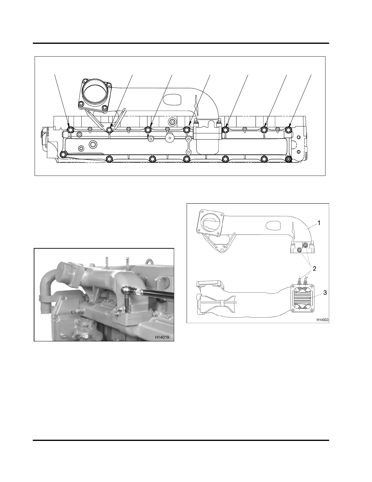
Figure 85 Intake manifold torque sequence
4. Torque intake manifold bolts including
the inlet
and EGR mixer support bolt (M10 x 90) to
the standard torque value (Genera
l Torque
Guidelines, page 445)andinthereco
mmended
sequence.
Figure 86 Torque t
he inlet and EGR mixer bolts
5. Torque four inle
t mixer bolts (M8 x 60) to
the standard to
rque value (General Torque
Guidelines, p
age445).
6. Install fuel as
sembly valve if removed, and tighten
to the special
torque value (Table 8).
7. Install intak
e plug assemblies, if removed (M12)
and tighten t
o the special torque value (Table 8).
Figure 87 Intake air heater – dual element
1. Inlet and EGR mixer
2. Intake air heater cable locations
3. Intake air heater element
See (TSI-05-12-35 New 1500 Watt Single Grid Intake
Air Heater Production Option, page466).
8. Connect Inlet Air Heater (IAH) cable(s).
EGES-265-2
Read all safety instructions in the "Safety Information" section of this manual before doing any procedures.
Follow all warnings, cautions, and notes.
© 2009 Navistar, Inc.
 Loading...


