– 552 –
CHAPTER 5 Operation Procedure for System with PIR
1.1 PIR Face Layout
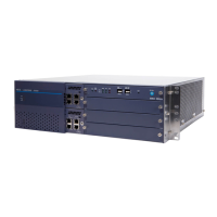
The figure below shows the slot configuration and the condition of mounted circuit card types for PIR.
Figure 5-1 Circuit card mounting of PIR
Note 1:
TSW will be mounted on the Slots 13 and 14 of PIR0 (1-IMG only).
Note 2: Faulty switch settings may cause system down, always handle it with care.
Corresponding alarm lamp is lit and system message is outputted when replacing the circuit card. Release
the alarm when circuit card replacement has completed. All system messages will be deleted when alarm
is released by the RALM command, read the system messages using the DFTD command when the system
messages are needed.
00 01 02 03 04 05 06 07 08 09 10 11 12 13 14 15 16 17 18 19 20 21 22
16 16 1616 3232 32 16 16 16 32 321616 16 1616
00 01 02 03 04 05 06 07 08 09 10 11 12 13 14 15 16 17 18 19 20 21 22
16 16 1616 3232 32 16 16 16 32 321616 16 1616
PWR (PWR #0)
DPWR (PWR #1)
TSW #0
TSW #1
Slot No.
Available Card Type
LT Connector Accommodations LT Connector Accommodations
LT Connector Accommodations LT Connector Accommodations
Number of Ports
Card Color
Slot No.
Available Card Type
Number of Ports
Card Color
Line/Trunk CardsLine/Trunk Cards
PWR (PWR #0)
DPWR (PWR #1)
MUX #0
MUX #1
Line/Trunk CardsLine/Trunk Cards
PIR 0 (1-IMG)
PIR other than PIR0 (1-IMG)

 Loading...


