8
Names and Functions of Parts
Cha
ter 1
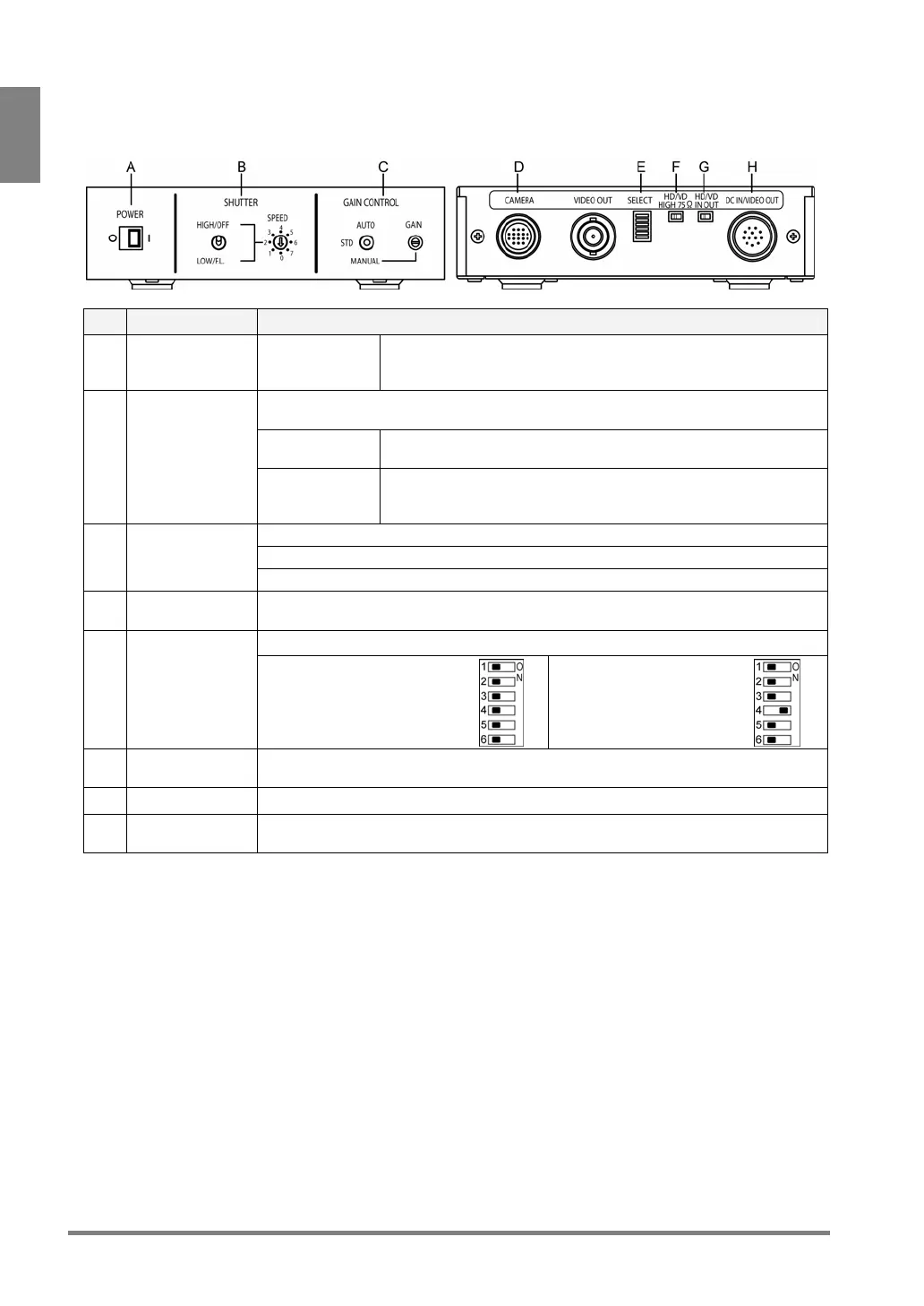
Camera Control Unit (hereafter called “CCU”)
<Front side> <Back side>
No. Name Description
A POWER
○: Power OFF
I : Power ON
Power switch for the camera. Turn ON this power switch before
supplying power to PV310. When power is on, green LED lights.
Use always in Power On status.
Shutter Speed setting switch. Available only in Field mode (when SELECT switch No.4
is ON).
Toggle switch
(left)
Use only with the setting to “HIGH/OFF” (upper).
B SHUTTER
Rotary switch
(right)
Sets the shutter speed of the number that the arrow points.
0: OFF (default), 1: 1/125s, 2: 1/250s, 3: 1/500s,
4: 1/1000s, 5: 1/2000s, 6: 1/4000s, 7: 1/10000s
STD: 0 dB fixed (default)
MANUAL: Adjusts Gain within the range of ± 6dB with GAIN volume.
C GAIN CONTROL
AUTO: Unavailable
D CAMERA port
(female)
Port for connecting a camera head with a camera head cable.
Switches between camera modes.
(*)
E SELECT
Frame mode (default):
Always use with the all
switches set to “OFF”.
Field mode:
Use with only No.4 switch
set to “ON”.
F HD/VD
impedance
Always use with the setting to “HIGH”, default value.
G HD/VD IN OUT Always use with the setting to “IN”, default value.
H DC IN/VIDEO
OUT port (male)
Connects to the Camera port of the PV310 with a camera cable (ANM842XX).
* When you changed the camera mode, change the camera mode of PV310 as well.