34
In
ut and Out
ut Interface Ports
Cha
ter 3
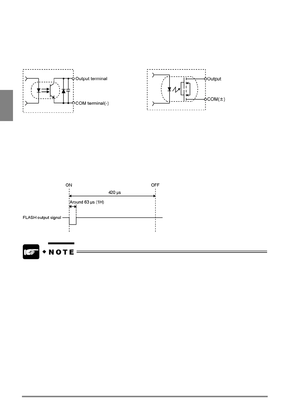
Flash Output Terminals
Do not commonly use COMMON for FLASH with other COMMON terminals.
Output Circuit: Product number with final number “N”
Rated operating voltage: 5 to 24 V DC
rated operational voltage: 5 to 24 V DC
Output Circuit: Product number with final number “P”
Rated operating voltage: 5 to 24 V DC
rated operational voltage: 5 to 24 V DC
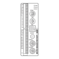
Flash Timing Chart
Note that the time from the FLASH output signal ON to the emission completion (including the times listed below)
does not exceed 420 s.
• Flash output sync. Signal lag of PV310. This signal lag changes depending on the attached strobe.
• Strobe response time. The time differs depending on the used strobe.
• Strobe flash time. The time differs depending on the used strobe.
• Set the shutter speed of a double speed random camera within the range from 1/30 to 1/1000 when
using a strobe light.
• You cannot use the same strobe light to the cameras connected to each PV310.
• When a strobe is used, the strobe lights flash continuously during Live-image display. When making
settings and performing inspection by using a strobe light, switch to memory image display.