Spectrum Measurements
R&S
®
ESR
329User Manual 1175.7068.02 ─ 12
4. Optionally, define a description of the trace in the "Comment" field.
5. Activate tracing for the range by selecting "On" in the "Range <number> Use" field
for the corresponding range and trace.
The start and stop time edit fields are ready for input.
Note: The time values have full numerical resolution and are only rounded for dis-
play.
6. Define the starting point of the range within the period.
7. Define the stopping point for the range within the period. Make sure the value for
the stopping time is smaller than the length of the period.
8. To define further ranges for the same period in the same trace, repeat steps 5- 7
for the same trace.
To define further ranges for the same period in a different trace, repeat steps 4- 7
for a different trace.
9. If necessary, activate the configured traces in the "Trace" menu.
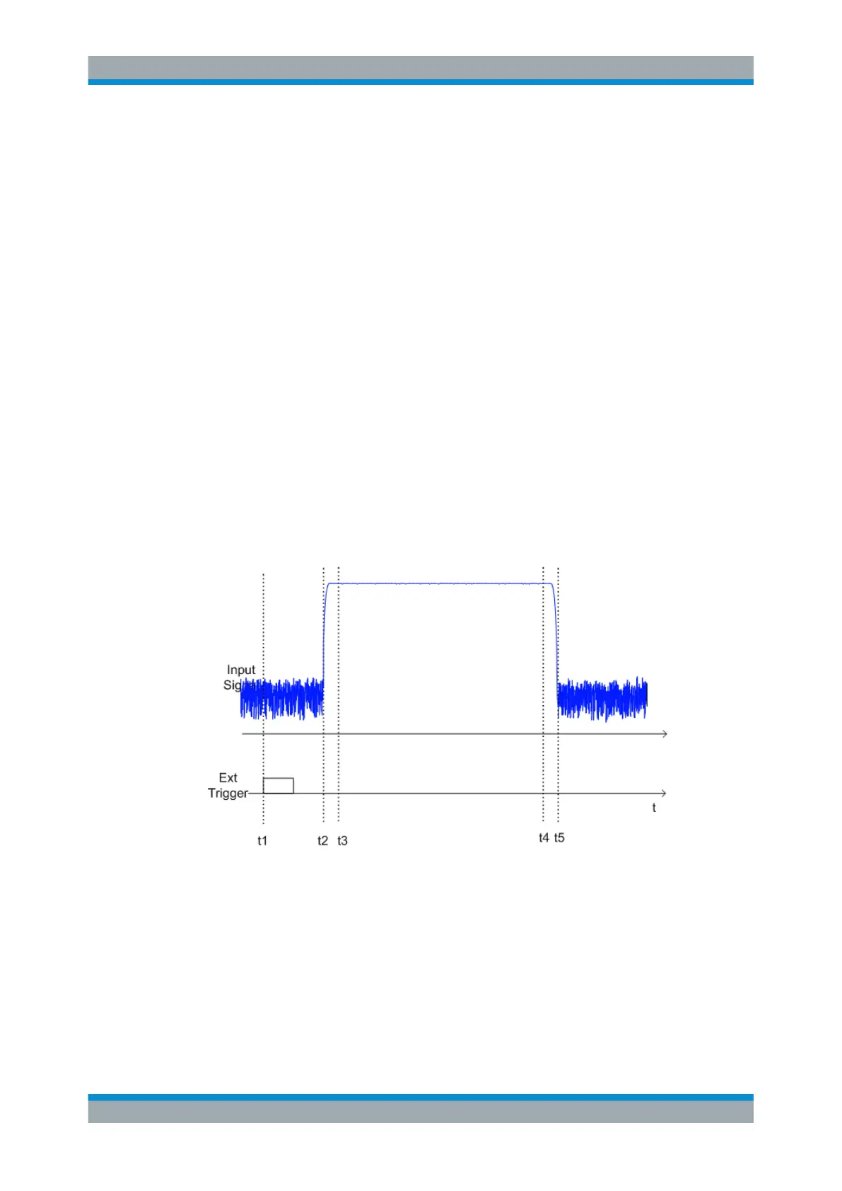
Gated statistics configuration example
A statistics evaluation has to be done over the useful part of the signal between t3 and
t4. The period of the GSM signal is 4.61536 ms
t1: External positive trigger slope
t2: Begin of burst (after 25 µs)
t3: Begin of useful part, to be used for statistics (after 40 µs)
t4: End of useful part, to be used for statistics (after 578 µs)
t5: End of burst (after 602 µs)
The instrument has to be configured as follows:
Measurements

 Loading...

