Tracking Generator
R&S
®
ESR
498User Manual 1175.7068.02 ─ 12
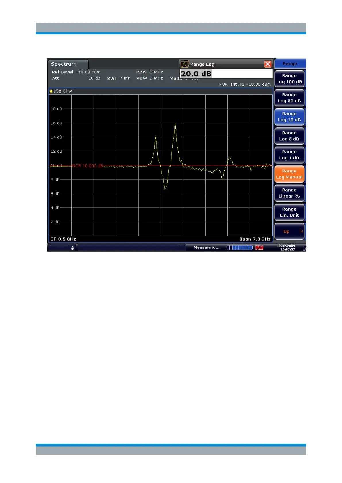
Figure 8-8: Measurement of a 10-dB attenuator pad with 2dB/Div
DISP:WIND:TRAC:Y:RVAL +10dB, see DISPlay[:WINDow<n>]:TRACe<t>:Y[:
SCALe]:RVALue on page 889
8.4.6 Modulation (internal Tracking Generator only)
The time characteristics of the tracking generator output signal can be influenced by
means of external signals (input voltage range -1 V to +1 V).
Two BNC connectors at the rear panel are available as signal inputs. Their function
changes depending on the selected modulation:
●
TG IN I/AMand
●
TG IN Q/FM
The modulation modes can be combined with each other and with the frequency offset
function up to a certain degree. The following table shows which modulation modes are
possible at the same time and which ones can be combined with the frequency offset
function.
Tracking Generator Functions
 Loading...