Spectrum Measurements
R&S
®
ESR
338User Manual 1175.7068.02 ─ 12
As a result, the zero span sweeps on all harmonics are shown, as well as the RMS
values and the THD (total harmonic distortion).
About Harmonics Distortion Measurement
Measuring the harmonics of a signal is a frequent problem which can be solved best
using a signal analyzer. In general, every signal contains harmonics which are larger
than others. Harmonics are particularly critical regarding high-power transmitters such
as transceivers because large harmonics can interfere with other radio services.
Harmonics are generated by nonlinear characteristics. They can often be reduced by
low pass filters. Since the signal analyzer has a nonlinear characteristic, e.g. in its first
mixer, measures must be taken to ensure that harmonics produced in the signal ana-
lyzer do not cause spurious results. If necessary, the fundamental wave must be selec-
tively attenuated with respect to the other harmonics with a high pass filter.
Obtainable dynamic range
When harmonics are being measured, the obtainable dynamic range depends on the
second harmonic intercept of the signal analyzer. The second harmonic intercept is the
virtual input level at the RF input mixer at which the level of the 2nd harmonic becomes
equal to the level of the fundamental wave. In practice, however, applying a level of
this magnitude would damage the mixer. Nevertheless, the available dynamic range for
measuring the harmonic distance of a DUT can be calculated relatively easily using the
second harmonic intercept.
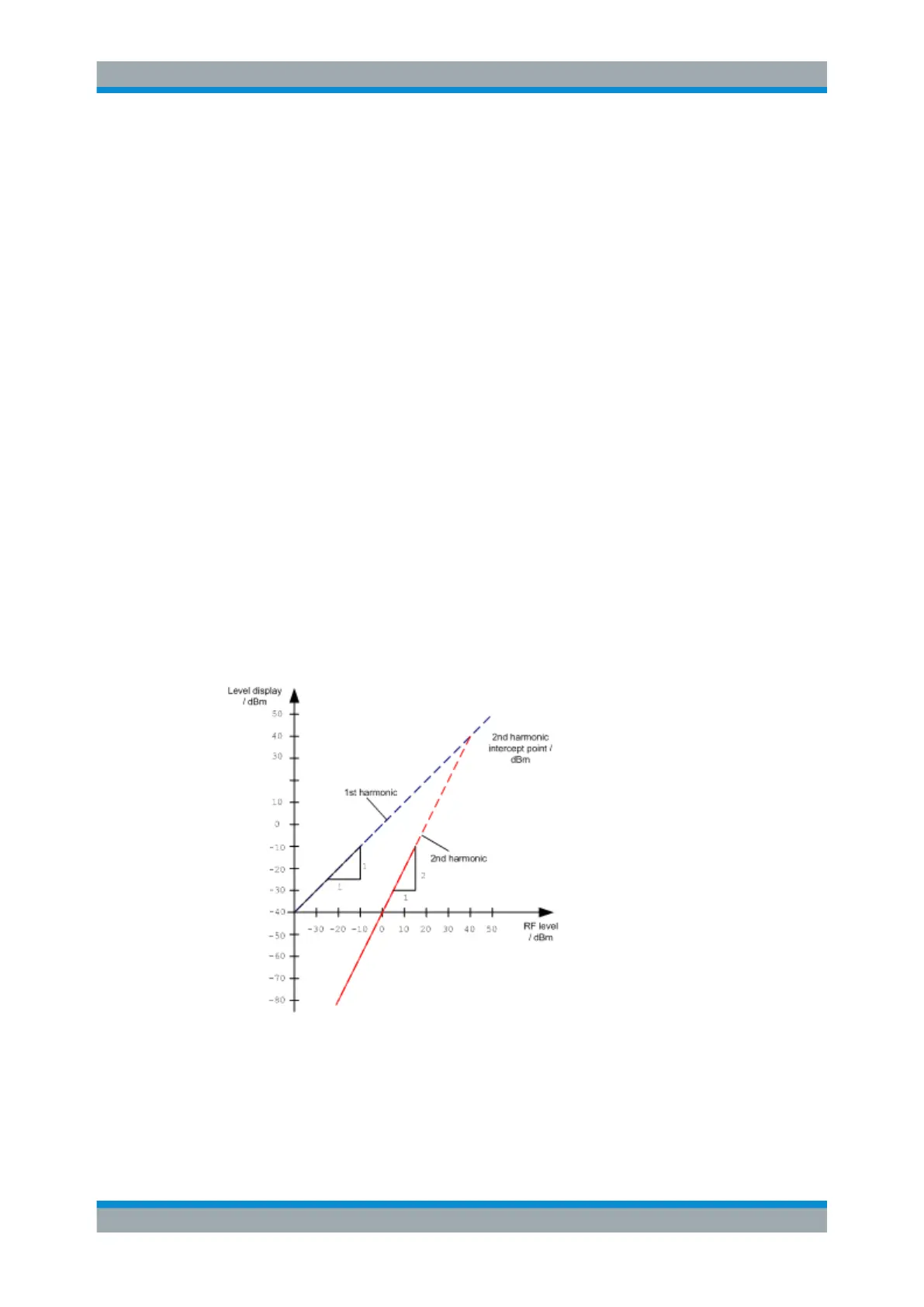
As shown in Figure 6-13, the level of the 2
nd
harmonic drops by 20 dB if the level of the
fundamental wave is reduced by 10 dB.
Figure 6-13: Extrapolation of the 1st and 2nd harmonics to the 2nd harmonic intercept at 40 dBm
The following formula for the obtainable harmonic distortion d
2
in dB is derived from the
straight-line equations and the given intercept point:
d
2
= S.H.I – P
I
(1)
Measurements
 Loading...