Tracking Generator
R&S
®
ESR
500User Manual 1175.7068.02 ─ 12
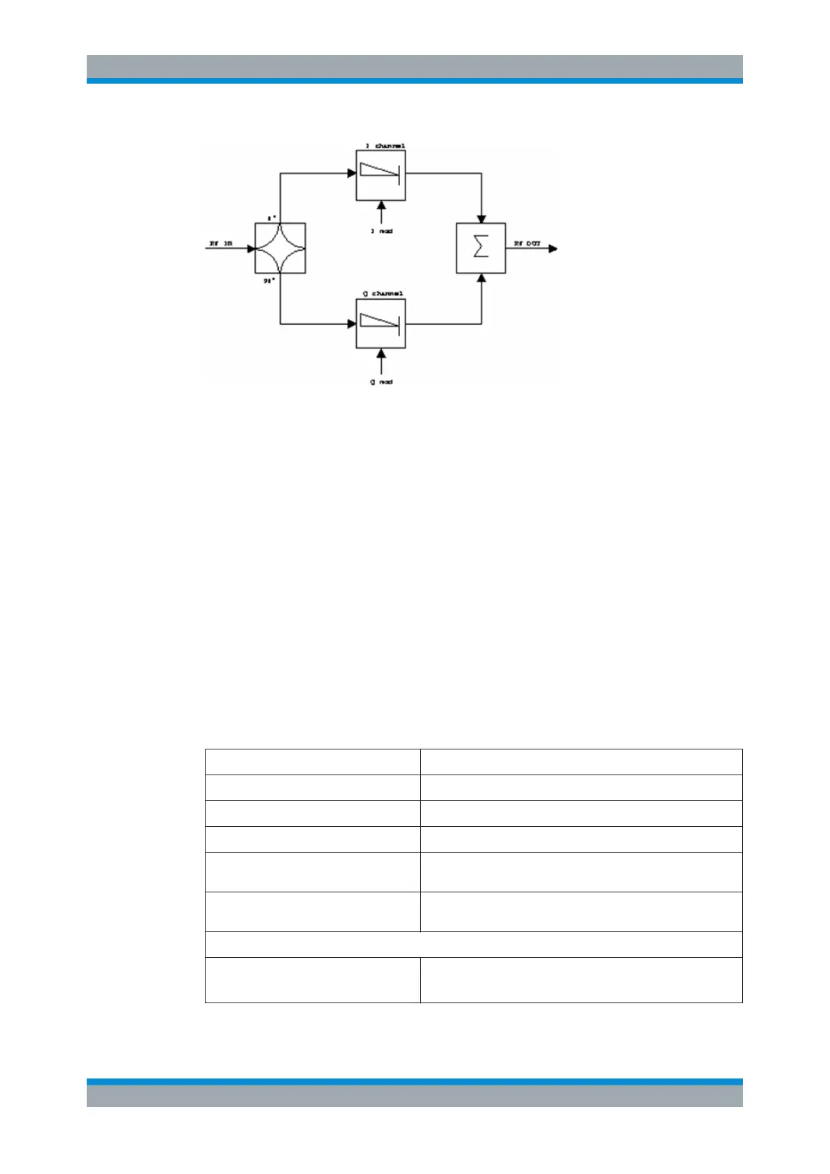
Figure 8-9: I/Q modulation
I/Q modulation is performed by means of the built-in quadrature modulator. The RF sig-
nal is divided into two orthogonal I and Q components (in phase and quadrature
phase). Amplitude and phase are controlled in each path by the I and Q modulation
signal. By adding the two components an RF output signal is generated that can be
controlled in amplitude and phase.
Remote command:
SOURce<n>:DM:STATe on page 903
8.5 Displayed Information and Errors
Diagram header
In Tracking Generator measurement mode, some additional information is displayed in
the diagram header.
Label Description
INT TG: <source power> Internal tracking generator active
INT TG: <start power>… <stop power> Internal tracking generator with power sweep active
EXT TG <1|2>: <source power> External tracking generator (1 or 2) active
LVL Power Offset (see Chapter 8.3, "Configuring Tracking Genera-
tors", on page 485
FRQ Frequency Offset (see Chapter 8.3, "Configuring Tracking Gen-
erators", on page 485
Measurement accuracy levels
NOR Normalization on;
No difference between reference setting and measurement
Displayed Information and Errors

 Loading...