R&S
®
ZVA / R&S
®
ZVB / R&S
®
ZVT GUI Reference
Channel Menu
Operating Manual 1145.1084.12 – 30 243
A power variation affects all source ports used in the active channel. Use the Port Configuration dialog
to modify the output power ranges for the individual analyzer ports. If a specific port power is selected as a
stimulus axis in the Channel – Mode – Port Configuration – Stimulus dialog, the actual port power
(including possible power offsets) is displayed, however, a power variation still changes the channel base
power.
Output power at the test ports
Power sets the output power at the test ports that supply the stimulus for the active channel. The channel
power can be varied over a wide dynamic range; the range can be further increased by means of
generator step attenuators. This leaves enough flexibility to include an attenuation or gain in the test
setup.
The channel power can be modified by the following settings:
Generator step attenuators decrease the output power by a definite factor a
step
. a
step
can be set
individually for all test ports but should not change during a sweep. To ensure a sufficient dynamic
range at the test ports, it is recommended to use automatic generator step attenuator setting.
The Source section of the Port Configuration dialog provides a port-specific constant power offset
(for arbitrary sweeps) and a port and frequency-dependent power slope factor (for frequency
sweeps).
A generator (source) power calibration generally modifies the channel power so that Power is
equal to the power at the calibrated reference plane.
The Port <port_no> Source Power dialog gives an overview of all power settings.
SOURce<Ch>:POWer[:LEVel][:IMMediate][:AMPlitude]
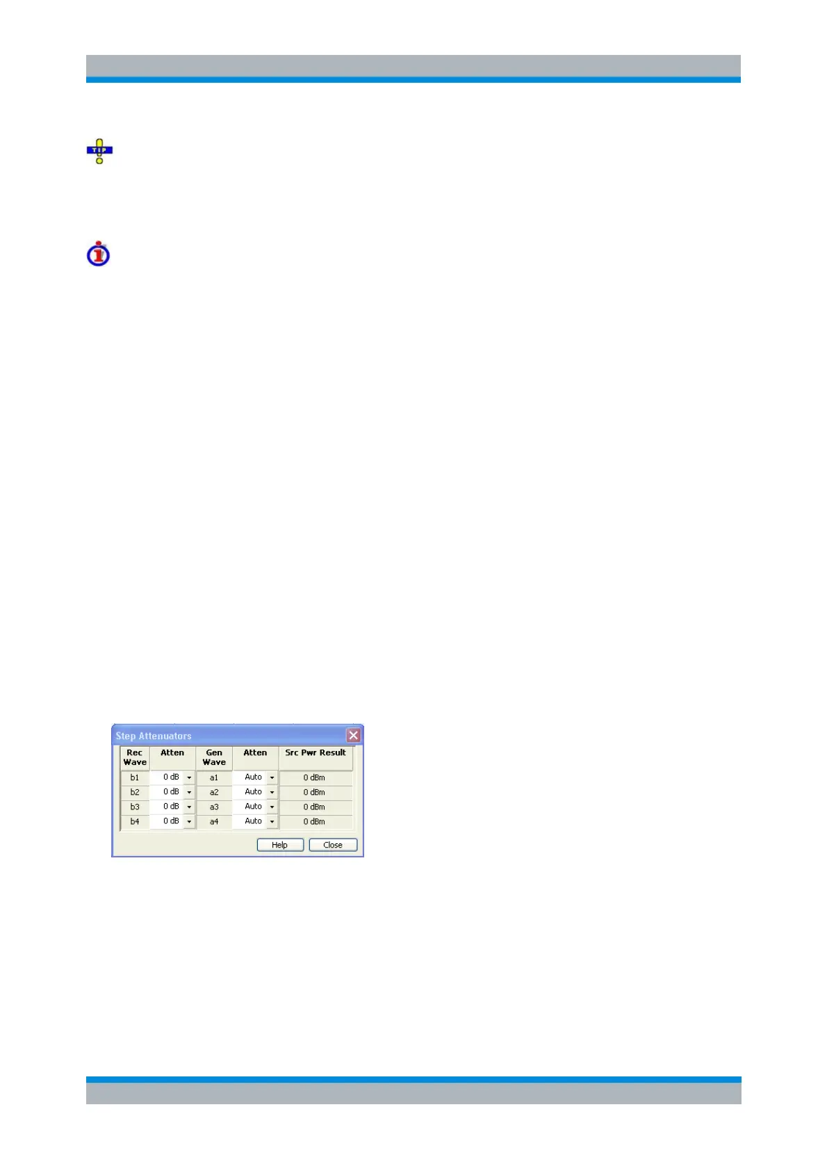
Step Attenuators (R&S ZVA, R&S ZVT20, and R&S ZVB Analyzers)
Opens a dialog to set the attenuation for the received and generated waves. The generator attenuation
can be set automatically; see Automatic generator attenuation below. Step attenuators can also improve
the measurement accuracy for special test scenarios; see "Low Noise" generator attenuation mode.
The Step Attenuators dialog contains the following columns:
Rec. Wave lists the received waves b
1
to b
n
. n is equal to the total number of test ports of the
analyzer.
Attenuation is used to enter the attenuation for each wave b
n
.
Gen. Wave lists the generated waves a
1
to a
n
.
Attenuation is used to enter the attenuation for each wave a
n
. If Auto is selected, the analyzer
automatically optimizes the generator attenuation according to the current channels settings. "Low