RL78/G1H CHAPTER 6 CLOCK GENERATOR
R01UH0575EJ0120 Rev. 1.20 Page 132 of 920
Dec 22, 2016
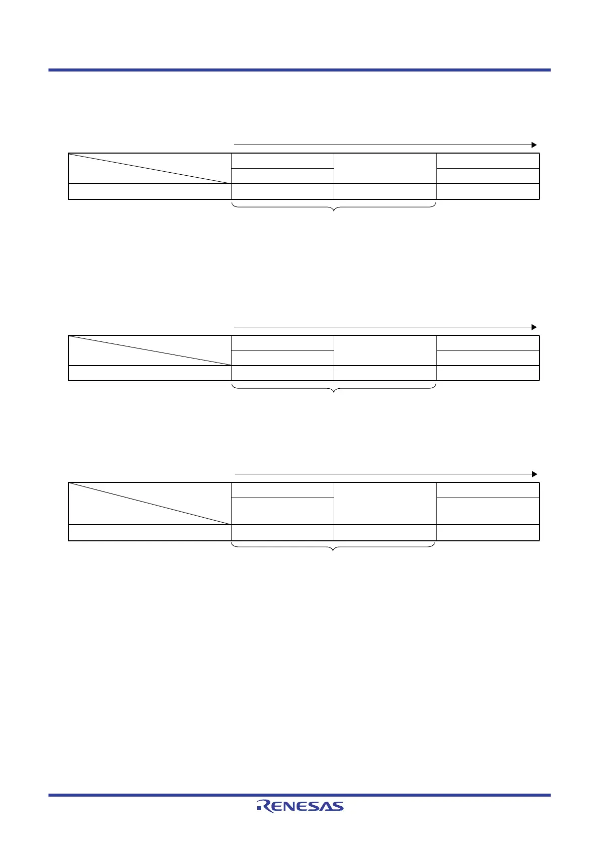
Table 6 - 5 CPU Clock Transition and SFR Register Setting Examples (3/5)
(6) CPU clock changing from high-speed system clock (C) to high-speed on-chip oscillator clock (B)
Note 18 to 65 μs
Remark The oscillation accuracy stabilization time changes according to the temperature conditions and the STOP mode period.
(7) CPU clock changing from high-speed system clock (C) to subsystem clock (D)
(8) CPU clock changing from subsystem clock (D) to high-speed on-chip oscillator clock (B)
Note 18 to 65 μs
Remark 1. (A) to (J) in Tables 6 - 3 to 6 - 7 correspond to (A) to (J) in Figure 6 - 19.
Remark 2. The oscillation accuracy stabilization time changes according to the temperature conditions and the STOP mode period.
(Setting sequence of SFR registers)
Setting Flag of SFR Register CSC Register
Oscillation accuracy
stabilization time
CKC Register
Status Transition HIOSTOP MCM0
(C)
→ (B)
0
Note
0
Unnecessary if the CPU is operating with
the high-speed on-chip oscillator clock
(Setting sequence of SFR registers)
Setting Flag of SFR Register CSC Register
Waiting for Oscillation
Stabilization
CKC Register
Status Transition XTSTOP CSS
(C)
→ (D) 0 Necessary 1
Unnecessary if the CPU is operating with the subsystem
clock
(Setting sequence of SFR registers)
Setting Flag of SFR Register CSC Register
Waiting for Oscillation
Stabilization
CKC Register
Status Transition
HIOSTOP CSS
(D)
→ (B)
0
Note
0
Unnecessary if the CPU is operating with the high-
speed on-chip oscillator clock
 Loading...


