RL78/G1H CHAPTER 7 TIMER ARRAY UNIT
R01UH0575EJ0120 Rev. 1.20 Page 158 of 920
Dec 22, 2016
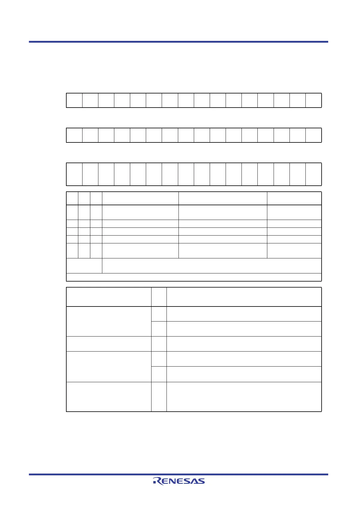
Figure 7 - 15 Format of Timer mode register mn (TMRmn) (4/4)
Note 1. Bit 11 is fixed to 0 of read only, write is ignored.
Note 2. In one-count mode, interrupt output (INTTMmn) when starting a count operation and TOmn output are not
controlled.
Note 3. If the start trigger (TSmn = 1) is issued during operation, the counter is initialized, and recounting is started
(does not occur the interrupt request).
Remark m: Unit number (m = 0, 1), n: Channel number (n = 0 to 3)
Address: F0190H, F0191H (TMR00) to F0196H, F0197H (TMR03), After reset: 0000H R/W
F01D0H, F01D1H (TMR10) to F01D6H, F01D7H (TMR13)
Symbol1514131211109876543210
TMRmn
(n = 2)
CKS
mn1
CKS
mn0
0
CCS
mn
MAST
ERmn
STS
mn2
STS
mn1
STS
mn0
CIS
mn1
CIS
mn0
00
MD
mn3
MD
mn2
MD
mn1
MD
mn0
Symbol1514131211109876543210
TMRmn
(n = 1, 3)
CKS
mn1
CKS
mn0
0
CCS
mn
SPLIT
mn
STS
mn2
STS
mn1
STS
mn0
CIS
mn1
CIS
mn0
00
MD
mn3
MD
mn2
MD
mn1
MD
mn0
Symbol1514131211109876543210
TMRmn
(n = 0)
CKS
mn1
CKS
mn0
0
CCS
mn
0
NoteNot
e 1
STS
mn2
STS
mn1
STS
mn0
CIS
mn1
CIS
mn0
00
MD
mn3
MD
mn2
MD
mn1
MD
mn0
MD
mn3
MD
mn2
MD
mn1
Operation mode of channel n Corresponding function Count operation of TCR
0 0 0 Interval timer mode Interval timer / Square wave output /
Divider function / PWM output (master)
Counting down
0 1 0 Capture mode Input pulse interval measurement Counting up
0 1 1 Event counter mode External event counter Counting down
1 0 0 One-count mode Delay counter / PWM output (slave) Counting down
1 1 0 Capture & one-count mode Measurement of high-/low-level width of
input signal
Counting up
Other than
above
Setting prohibited
The operation of each mode varies depending on MDmn0 bit (see table below).
Operation mode
(Value set by the MDmn3 to MDmn1 bits
(see table above))
MD
mn0
Setting of starting counting and interrupt
• Interval timer mode (0, 0, 0)
• Capture mode (0, 1, 0)
0 Timer interrupt is not generated when counting is started
(timer output does not change, either).
1 Timer interrupt is generated when counting is started
(timer output also changes).
• Event counter mode (0, 1, 1) 0 Timer interrupt is not generated when counting is started
(timer output does not change, either).
• One-count mode
Note 2
(1, 0, 0)
0 Start trigger is invalid during counting operation.
At that time, interrupt is not generated.
1
Start trigger is valid during counting operation
Note 3
.
At that time, interrupt is not generated.
• Capture & one-count mode (1, 1, 0) 0 Timer interrupt is not generated when counting is started
(timer output does not change, either).
Start trigger is invalid during counting operation.
At that time, interrupt is not generated.
 Loading...


