RL78/G1H CHAPTER 13 A/D CONVERTER
R01UH0575EJ0120 Rev. 1.20 Page 289 of 920
Dec 22, 2016
Note 2. The following time is the maximum amount of time necessary to start conversion.
For the second and subsequent conversion in sequential conversion mode, the stabilization wait time for A/D power
supply do not occur in hardware trigger wait mode.
Caution 1. If using the hardware trigger wait mode, setting the ADCS bit to 1 is prohibited (but the bit is automatically
switched to 1 when the hardware trigger signal is detected). However, it is possible to clear the ADCS bit to 0 to
specify the A/D conversion standby status.
Caution 2. While in the one-shot conversion mode of the hardware trigger no-wait mode, the ADCS flag is not automatically
cleared to 0 when A/D conversion ends. Instead, 1 is retained.
Caution 3. Only rewrite the value of the ADCE bit when ADCS = 0 (while in the conversion stopped/conversion standby
status).
Caution 4. To complete A/D conversion, specify at least the following time as the hardware trigger interval:
Hardware trigger no wait mode: 2 f
CLK clock + Conversion start time + A/D conversion time
Hardware trigger wait mode: 2 f
CLK clock + Conversion start time + A/D power supply stabilization wait time +
A/D conversion time
Remark
fCLK: CPU/peripheral hardware clock frequency
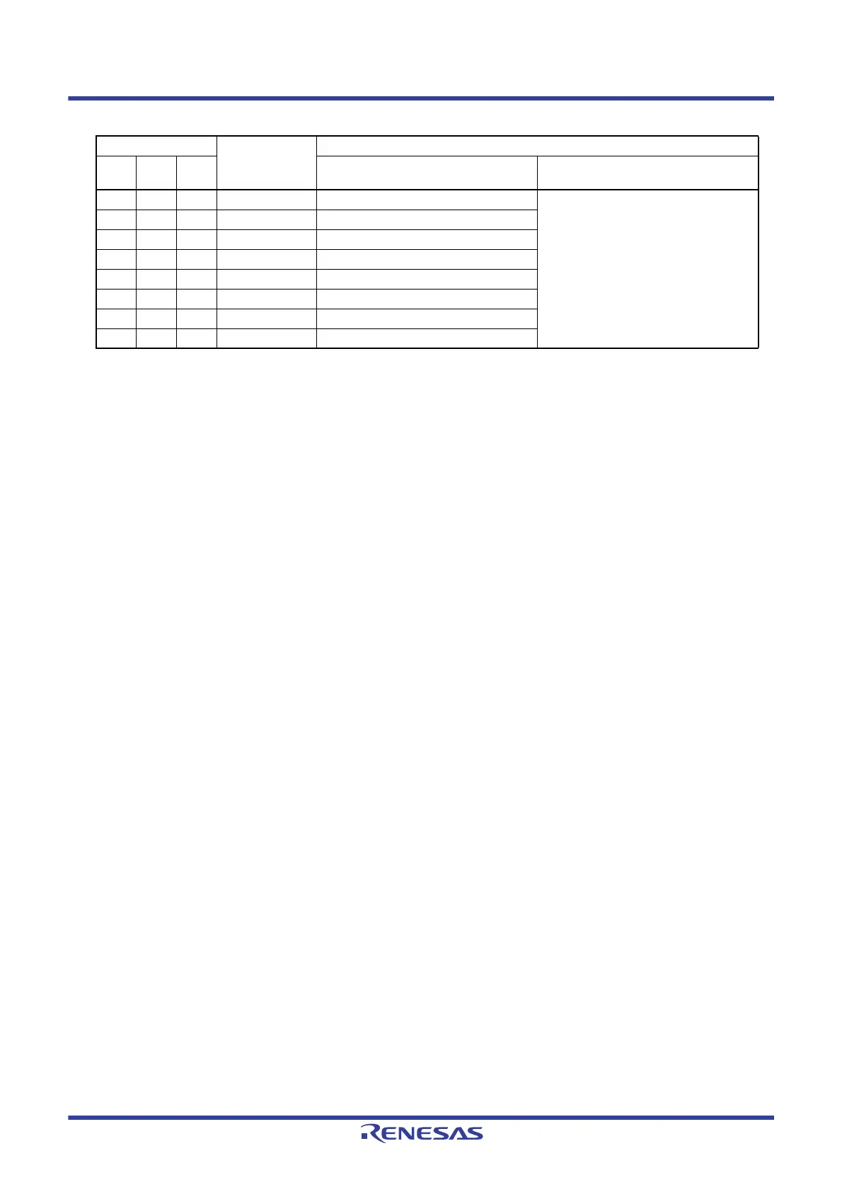
ADM0
Conversion Clock
(f
AD)
Conversion Start Time (Number of f
CLK Clocks)
FR2 FR1 FR0
Software trigger mode/
Hardware trigger no wait mode
Hardware trigger wait mode
000 f
CLK/64 63 1
001 f
CLK/32 31
010 f
CLK/16 15
011 f
CLK/8 7
100 f
CLK/6 5
101 f
CLK/5 4
110 f
CLK/43
111 f
CLK/2 1
 Loading...


