RL78/G1H CHAPTER 26 OPTION BYTE
R01UH0575EJ0120 Rev. 1.20 Page 803 of 920
Dec 22, 2016
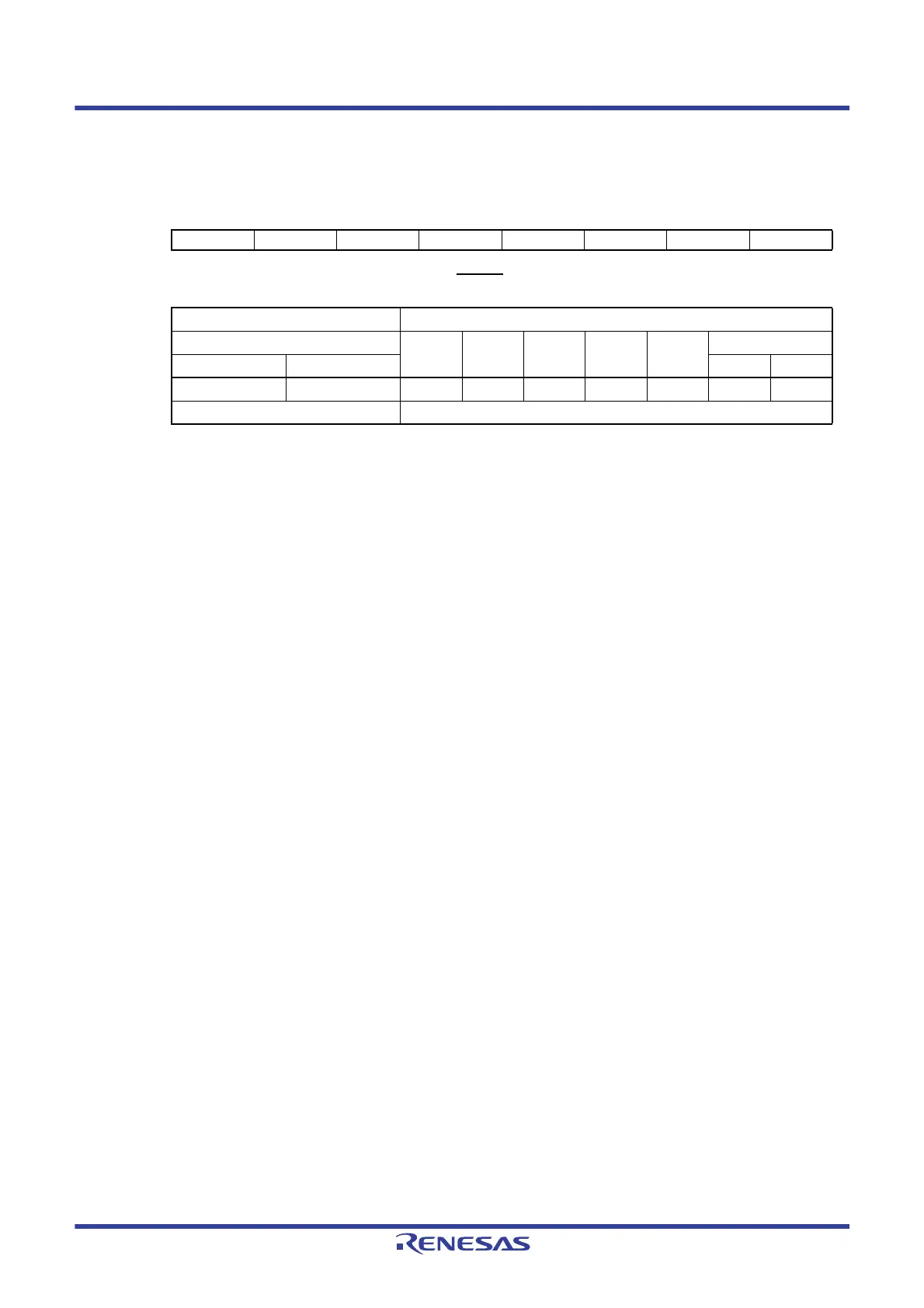
Figure 26 - 5 Format of User Option Byte (000C1H/010C1H) (4/4)
• LVD off setting (external reset input from the RESET
pin is used)
Note Set the same value as 000C1H to 010C1H when the boot swap operation is used because 000C1H is
replaced by 010C1H.
Caution 1. Be sure to set bit 4 to “1”.
Caution 2. After power is supplied, the reset state must be retained until the operating voltage becomes in the
range defined in 31.4 AC Characteristics. This is done by utilizing the voltage detection circuit or
controlling the externally input reset signal. After the power supply is turned off, this LSI should be
placed in the STOP mode, or placed in the reset state by utilizing the voltage detection circuit or
controlling the externally input reset signal, before the voltage falls below the operating range. The
range of operating voltage varies with the setting of the user option byte (000C2H or 010C2H).
Remark 1. ×
: Don’t care
Remark 2. For details on the LVD circuit, see CHAPTER 23 VOLTAGE DETECTOR.
Remark 3. The detection voltage is a typical value. For details, see 31.6.3 LVD characteristics.
Address: 000C1H/010C1H
Note
76543210
VPOC2 VPOC1 VPOC0 1 LVIS1 LVIS0 LVIMDS1 LVIMDS0
Detection voltage Option byte Setting Value
V
LVD
VPOC2 VPOC1 VPOC0 LVIS1 LVIS0
Mode setting
Rising edge Falling edge LVIMDS1 LVIMDS0
——1
×××××1
— Settings other than the above are prohibited
 Loading...


