Service
272 SICAM RTUs, User Manual SICAM CMIC
DC8-001-2.09, Edition 08.2016
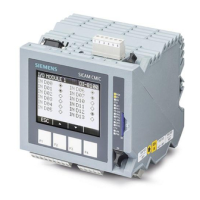
6.1 Operation and Display Elements
The operation and display elements are located on the front of the housing.
6.1.1 LED Display
The LED display comprises
• System status
─ 3 LEDs for operating states of the system
• Communication status
─ 2 LEDs each for the states of the
4 communication interfaces (dependent on the
configured protocol elements)
Meaning of the subsequently represented symbols:
Symbol Status Symbol Status
˜
Active
§
Flashes regularly
™
Inactive
V
Flashes irregularly
ž
Flickers (data exchange) x Not relevant
F4F3F2F1
RY
ER
RS-232
OH2
OH3
SD
X4
Display
Keys
RY
ER
RS-232
OH2
OH3
SD
 Loading...