4.11 Test Run Checklist
140 YASKAWA ELECTRIC SIEP C710616 27G YASKAWA AC Drive A1000 Technical Manual
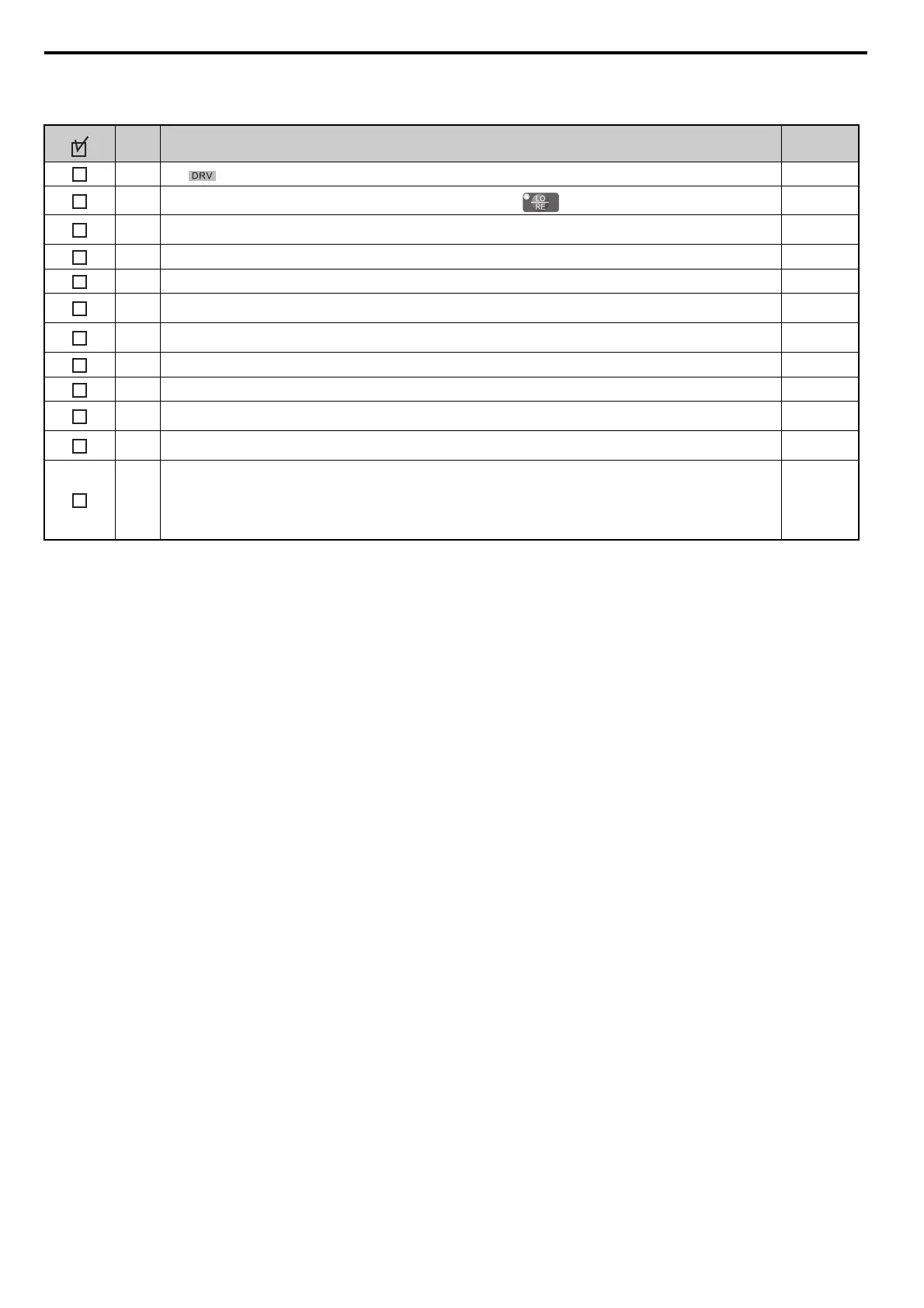
Proceed to the following checklist after checking items 5 through 20.
No. Checklist Page
21
The should light after giving a Run command.
–
22
To give a Run command and frequency reference from the digital operator, press to set to LOCAL. The LO/RE key will light.
99, 108
23
If the motor rotates in the opposite direction during the test run, switch two of the drive output terminals (U/T1, V/T2, W/T3) or change
parameter b1-14.
370
24 In accordance with load condition, set Heavy Duty or Normal Duty mode using C6-01. Heavy Duty is the default setting. 195
25 Set the correct values for the motor rated current (E2-01, E4-01, E5-03) and motor protection (L1-01) to ensure motor thermal protection. 216, 267
26
If the Run command and frequency reference are provided via the control circuit terminals, set the drive for REMOTE and be sure the LO/RE
light is out.
108
27
If the control circuit terminals should supply the frequency reference, select the correct voltage input signal level (0 to 10 V or -10 to +10 V)
or the correct current input signal level (4 to 20 mA or 0 to 20 mA).
148
28 Apply the proper signal level (-10 to +10 V or 0 to 10 V) to terminal A1, A2, or A3. 148
29 Apply the proper signal level (-10 to +10 V, 4 to 20 mA or 0 to 20 mA) to terminal A2. 148
30
Set the level for current signal to H3-09 (set to 2 for 4 to 20 mA, or 3 for 0 to 20 mA). Set terminal A2 function to H3-10 (set to 0 for
Frequency Bias).
148
31
Set DIP switch S1 on the drive to “I” when using terminal A2 as current input.
Set DIP switch S1 on the drive to “V” when using terminal A2 as voltage input.
–
32
If the frequency reference is supplied via one of the analog inputs, make sure the analog input produces the desired frequency reference. Make
the following adjustments if the drive does not operate as expected:
Gain adjustment: Set the maximum voltage/current signal and adjust the analog input gain (H3-03 for input A1, H3-11 for input A2, H3-07
for analog input A3) until the frequency reference value reaches the desired value.
Bias adjustment: Set the minimum voltage/current signal and adjust the analog input bias (H3-04 for input A1, H3-12 for input A2, H3-08 for
analog input A3) until the frequency reference value reaches the desired minimum value.
257, 259
 Loading...


