5.2 b: Application
YASKAWA ELECTRIC SIEP C710616 27G YASKAWA AC Drive A1000 Technical Manual 149
Current Input
Input terminal A2 can accept a current input signal. Refer to Table 5.6 to set terminal A2 for current input.
Table 5.6 Analog Input Settings for Frequency Reference Using a Current Signal
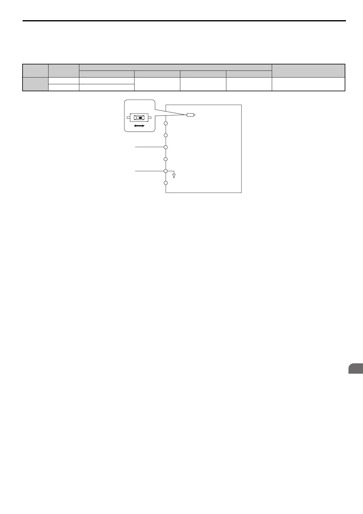
Figure 5.2
Figure 5.2 Setting the Frequency Reference as a Current Signal to Terminal A2
DIP switch S1 must first be set for current input.
Switching between Main/Auxiliary Frequency References
The frequency reference input can be switched between the analog terminals A1, A2, and A3 using multi-speed inputs.
Refer to Multi-Step Speed Selection on page 198 for details on using this function.
Setting 2: MEMOBUS/Modbus Communications
This setting requires entering the frequency reference via the RS-485/422 serial communications port (control terminals
R+, R-, S+, and S-). Refer to MEMOBUS/Modbus Communications on page 545 for instructions.
Setting 3: Option card
This setting requires entering the frequency reference via an option board plugged into connector CN5-A on the drive
control board. Consult the option board manual for instructions on integrating the drive with the communication system.
Note: If the frequency reference source is set for an option PCB (b1-01 = 3), but an option board is not installed, an oPE05 Operator
Programming Error will be displayed on the digital operator and the drive will not run.
Setting 4: Pulse Train Input
When b1-01 is set to 4, the frequency reference must be provided by a pulse train signal to terminal RP. Follow the
directions below to make sure the pulse train signal is working properly.
Verifying Pulse Train is Working Properly
• Make sure that b1-01 is set to 4 and H6-01 is set to 0.
• Set the pulse input scaling H6-02 to the pulse train frequency
value that equals 100% of the frequency reference.
• Enter a pulse train signal to terminal RP and check if
the correct frequency reference is displayed.
Terminal Signal Level
Parameter Settings
Notes
Signal Level Selection Function Selection Gain Bias
A2
4 to 20 mA H3-09 = 2
H3-10 = 0
(Frequency Bias)
H3-11 H3-12
Make sure to set DIP switch S1 on the
te
rminal board to “I” for current input.
0 to 20 mA H3-09 = 3
Drive
A1 Analog Input 1
0 or 4 to 20 mA
AC Analog input common
+V
-V
10.5 V, 20 mA power supply
-10.5 V, 20 mA power supply
A2 Analog Input 2
A3 Analog Input 3
DIP switch S1
VI