5.3 C: Tuning
184 YASKAWA ELECTRIC SIEP C710616 27G YASKAWA AC Drive A1000 Technical Manual
Switching Acceleration and Deceleration Times by Motor Selection
When switching between motor 1 and 2 using a digital input (H1-= 16), parameters C1-01 to C1-04 become accel/
decel time 1 and 2 for motor 1, while C1-05 to C1-08 become accel/decel time 1 and 2 for motor 2. Accel/decel times 1
and 2 can be switched for each motor using a digital inputs set to H1- = 7 like shown in Table 5.14.
Note: 1. The motor 2 selection function cannot be used when PM motor is used.
2. The digital input setting “Accel/Decel time 2 selection” (H1- = 1A) cannot be used together with motor 1/2 switching. Trying to
do so triggers an oPE03 error, indicating a contradictory multifunction input settings.
Table 5.14 Motor Switching and Accel/Decel Time Combinations
Switching Accel/Decel Times by a Frequency Level
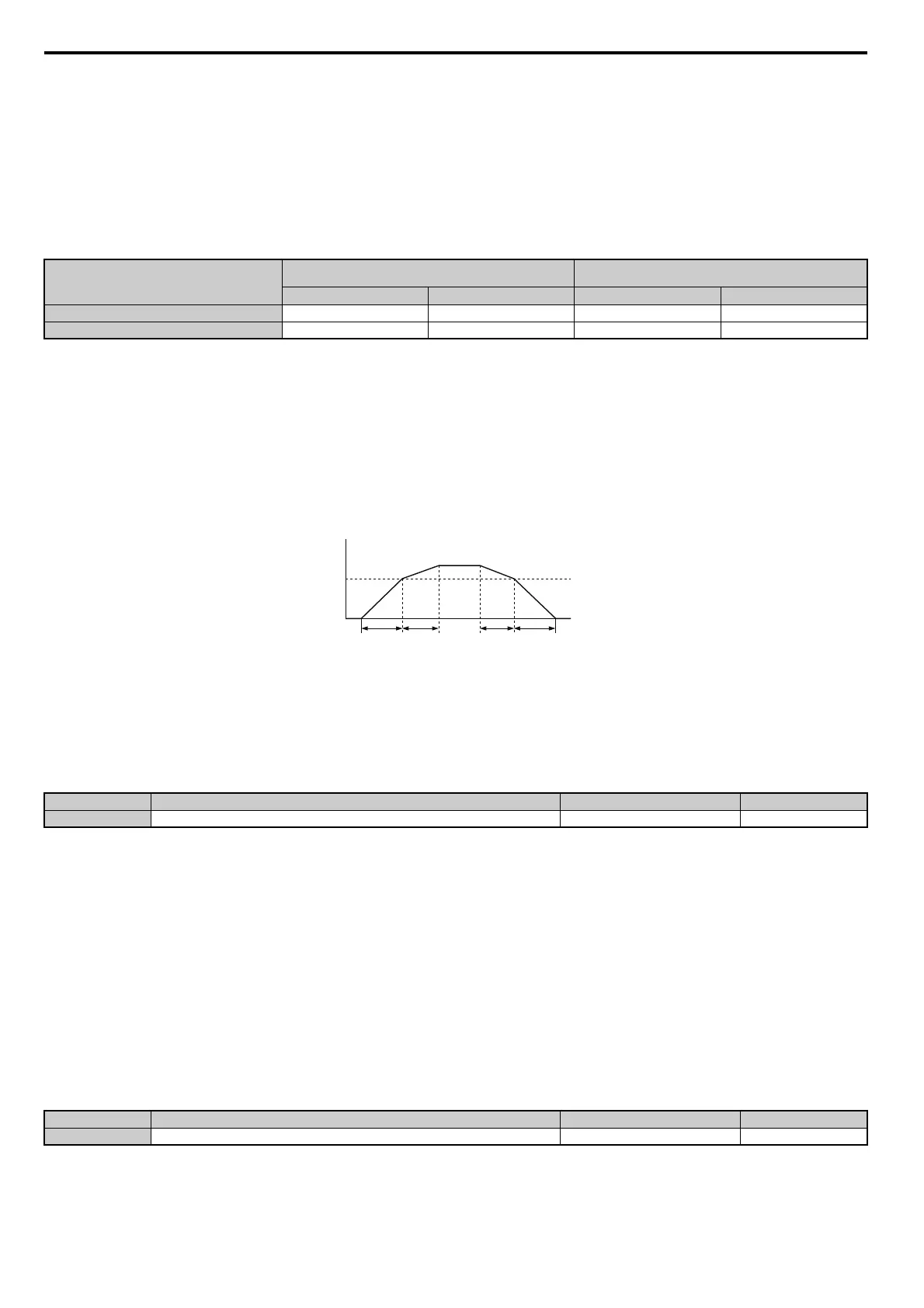
The drive can switch between different acceleration and deceleration times automatically. The drive will switch from
accel/decel time 4 in C1-07 and C1-08 to the default accel/decel time in C1-01 and C1-02 (C1-05 and C1-06 for motor 2)
when the output frequency exceeds the frequency level set in parameter C1-11. When it falls below this level, the accel/
decel times are switched back. Figure 5.34 shows an operation example.
Note: Acceleration and deceleration times selected by digital inputs have priority over the automatic switching by the frequency level
set to C1-11. For example, if accel/decel time 2 is selected, the drive will use this time only and not switch from accel/decel time
4 to the selected one.
Figure 5.34
Figure 5.34 Accel/Decel Time Switching Frequency
C1-11: Accel/Decel Time Switching Frequency
Sets the frequency at which the drive switches between accel/decel time settings. Refer to Switching Accel/Decel Times
by a Frequency Level on page 184.
Note: Setting C1-11 to 0.0 Hz (0.0%) disables this function.
C1-09: Fast Stop Time
Parameter C1-09 will set a special deceleration that is used when certain faults occur or that can be operated by closing a
digital input configured as H1- = 15 (N.O. input) or 17 (N.C. input). A momentary closure of the input terminal wi
ll
trigger the Fast Stop operation; it does not need to be closed continuously.
It is not possible to restart the drive after initiating
a Fast Stop operation until after completing deceleration, clearing the
Fast Stop input, and cycling the Run command.
A digital output programmed for “During Fast Stop” (H2- = 4C) will be closed as long as Fast Stop is active.
A Fast Stop can be selected as the action the drive should take whe
n certain faults occur, such as L8-03 (Overheat
Pre-Alarm Operation Selection).
NOTICE: Rapid deceleration can trigger an overvoltage fault. When faulted, the drive output shuts off, and the motor coasts. To avoid
Accel/Decel Time 1 (H1- = 7)
Motor 1 Selected
(Terminal set to H1- = 16 OFF)
Motor 2 Selected
(Terminal set to H1- = 16 ON)
Accel Decel Accel Decel
Open C1-01 C1-02 C1-05 C1-06
Closed C1-03 C1-04 C1-07 C1-08
No. Parameter Name Setting Range Default
C1-11
<1> In AOLV/PM and CLV/PM control modes, the setting units and range are expressed as a percent (0.0 to 100.0%) instead of in Hz.
Accel/Decel Time Switching Frequency 0.0 to 400.0 Hz <1> Determined by A1-02 <1>
No.
<1> The setting range for the Fast Stop Time is determined by the accel/decel time setting units in C1-10. For example, if the time is set in units of
0.01 s (C1-10 = 0), the setting range becomes 0.00 to 600.00 s
Parameter Name Setting Range Default
C1-09 Fast Stop Time 0.0 to 6000.0 s <1> 10.0 s
Output Frequency
C1-11
Accel/Decel Time
Switch Frequency
C1-07
setting
When the output frequency ≥ C1-11, drive uses Accel/Decel Time 1 (C1-01, -02)
When the output frequency < C1-11, drive uses Accel/Decel Time 2 (C1-07, -08)
C1-01
setting
C1-02
setting
C1-08
setting