5.3 C: Tuning
192 YASKAWA ELECTRIC SIEP C710616 27G YASKAWA AC Drive A1000 Technical Manual
C5-01, C5-03/C5-02, C5-04: ASR Proportional Gain 1, 2 / ASR Integral Time 1, 2
These parameters can be used to adjust the responsiveness of the ASR.
Note: C5-01 is automatically set when ASR Tuning is performed (T1-01 = 9 or T2-01 = 9).
These parameter settings will function differently depending on the control mode.
V/f Control with PG
Parameters C5-01 and C5-02 determine the ASR characteristics at maximum speed, whereas C5-03 and C5-04 determine
the characteristics at minimum speed.
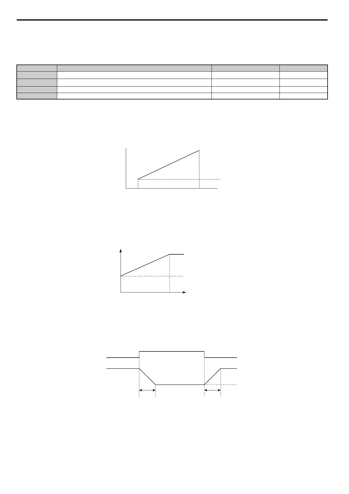
Figure 5.40
Figure 5.40 ASR Gain and Integral Time in V/fw/PG
CLV, AOLV/PM, and CLV/PM
In these control modes, parameters C5-03 and C5-04 define the ASR gain an integral time at zero speed. The settings in
C5-01 and C5-02 are used at speeds above the setting in C5-07. C5-07 is set to 0 as the default so that C5-01 and C5-02
are used over the entire speed range. Also refer to C5-07: ASR Gain Switching
Frequency on page 193.
Figure 5.41
Figure 5.41 Low-speed and High-speed Gain Settings
The gain set in C5-03 can also be activated with a digital input programmed to “ASR gain switch” (H1- = 77). When
the terminal is open, the drive uses the ASR gain level set by the pattern in the figure above. When the terminal closes,
C5-03 is used. The integral time set to C5-02 is used to change linearly between these settings.
The ASR gain switch command from a multi-function
input terminal overrides the switching frequency set to C5-07.
Figure 5.42
Figure 5.42 ASR Proportional Gain Switch
ASR Gain Tuning (C5-01, C5-03)
The higher this setting, the faster is the speed response. Too high of a setting can lead to oscillation. In general, this
setting should be increased with larger loads in order to minimize the speed deviation.
ASR Integral Time Tuning (C5-02, C5-04)
Determines how fast a continuous speed deviation problem is eliminated. Too long of an integral time makes the speed
control less responsive, while a too short of an integral time can cause oscillation.
No. Parameter Name Setting Range Default
C5-01
ASR Proportional Gain 1
0.00 to 300.00 Determined by A1-02
C5-02
ASR Integral Time 1
0.000 to 10.000 s Determined by A1-02
C5-03 ASR Proportional Gain 2 0.00 to 300.00 Determined by A1-02
C5-04 ASR Integral Time 2 0.000 to 10.000 s Determined by A1-02
E1-04
0
P = C5-03
I = C5-04
P = C5-01
I = C5-02
E1-09
P and I setting
Motor speed
Max. output frequency
Min. output frequency
P, I
P = C5-01
I = C5-02
P = C5-03
I = C5-04
C5-07
㧜
Ramp
Motor speed (Hz)
(Low speed)
C5-02 C5-02
OFF
ON
ASR Gain Switch signal
(Digital input)
C5-03 gain setting
Proportional gain (P)
Proportional gain
determined
by motor speed.