5.3 C: Tuning
YASKAWA ELECTRIC SIEP C710616 27G YASKAWA AC Drive A1000 Technical Manual 193
C5-05: ASR Limit
Sets the ASR output limit as a percentage of the maximum output frequency (E1-04). If the motor rated slip is high, the
setting might need to be increased to provide proper motor speed control. Use the ASR output monitor U6-04 to
determine if ASR is working at the limit set in C5-05. If so, make sure the PG pulses (F1-01), PG gear teeth (F1-12,
F1-13), and the PG signal are set correctly before making further changes to C5-05.
C5-06: ASR Primary Delay Time Constant
This parameter sets the filter time constant for the time from the speed loop to the torque command output.
Increase this setting gradually in increments of
0.01 for loads with low rigidity, or when oscillation is a problem.
Note: This parameter rarely requires adjustment.
C5-07: ASR Gain Switching Frequency
Sets the frequency where the drive should switch between ASR proportional gain 1 and 2 (C5-01, C5-03) as well as
between integral time 1 and 2 (C5-02, C5-04).
Note: A multi-function input set for the ASR gain switch (H1- = 77) takes priority over the ASR gain switching frequency.
Switching the proportional gain and integral time in the low or high speed range can help stabilize operation and avoid
resonance problems. A good switching point is about 80% of the frequency where oscillation occurs, or at 80% of the
target speed. Refer to C5-01, C5-03/C5-02, C5-04: ASR Proportional Gain 1, 2 / ASR Integral Time 1, 2 on page 192.
C5-08: ASR Integral Limit
Sets the upper limit for ASR as a percentage of the rated load.
C5-12: Integral Operation during Accel/Decel (V/f w/PG)
Enables integral operation during acceleration and deceleration. Integral operation should be used when driving a heavy
load or a high inertia load, but can cause problems with overshoot at the end of acceleration and deceleration. Refer to
ASR Setup Problems and Corrective Actions on page 191 to solve such problems.
Setting 0: Disabled
Integral operation occurs only during constant speed and not during acceleration or deceleration.
Setting 1: Enabled
Integral operation is always enabled.
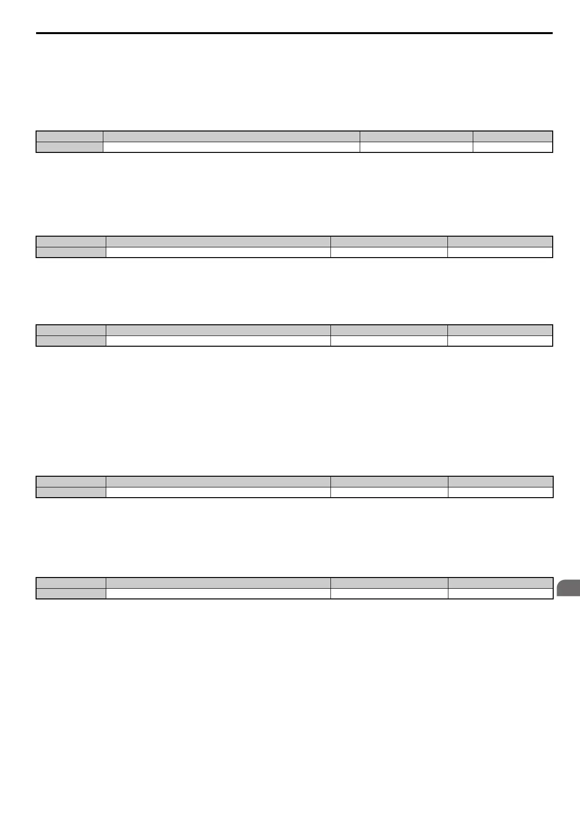
No. Parameter Name Setting Range Default
C5-05 ASR Limit 0.0 to 20.0% 5.0%
No. Parameter Name Setting Range Default
C5-06 ASR Primary Delay Time Constant 0.000 to 0.500 s Determined by A1-02
No. Parameter Name Setting Range Default
C5-07
<1> In AOLV/PM and CLV/PM control modes, the setting units and range are expressed as a percent (0.0 to 100.0%) instead of in Hz.
ASR Gain Switching Frequency 0.0 to 400.0 Hz <1> Determined by A1-02 <1>
No. Parameter Name Setting Range Default
C5-08 ASR Integral Limit 0 to 400% 400%
No. Parameter Name Setting Range Default
C5-12 Integral Operation during Accel/Decel 0, 1 0